


GE Multilin
L30 Line Current Differential System
5-179
5 SETTINGS
5.6 GROUPED ELEMENTS
5
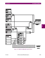
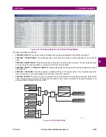
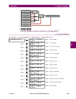
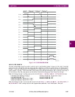
Figure 5–83: NEGATIVE-SEQUENCE OVERVOLTAGE SCHEME LOGIC
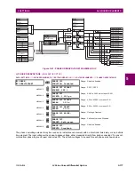
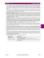
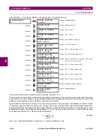
e) AUXILIARY UNDERVOLTAGE
(ANSI 27X, IEC PTUV)
PATH: SETTINGS
GROUPED ELEMENTS
SETTING GROUP 1(6)
VOLTAGE ELEMENTS
AUXILIARY UV1
The L30 contains one auxiliary undervoltage element for each VT bank. This element is intended for monitoring undervolt-
age conditions of the auxiliary voltage. The
AUX UV1 PICKUP
selects the voltage level at which the time undervoltage ele-
ment starts timing. The nominal secondary voltage of the auxiliary voltage channel entered under
SETTINGS
SYSTEM
SETUP
AC INPUTS
VOLTAGE BANK X5
AUXILIARY VT X5 SECONDARY
is the per-unit base used when setting the
pickup level.
The
AUX UV1 DELAY
setting selects the minimum operating time of the auxiliary undervoltage element. Both
AUX UV1 PICKUP
and
AUX UV1 DELAY
settings establish the operating curve of the undervoltage element. The auxiliary undervoltage element
can be programmed to use either definite time delay or inverse time delay characteristics. The operating characteristics
and equations for both definite and inverse time delay are as for the phase undervoltage element.
AUXILIARY UV1
AUX UV1
FUNCTION: Disabled
Range: Disabled, Enabled
MESSAGE
AUX UV1 SIGNAL
SOURCE: SRC 1
Range: SRC 1, SRC 2
MESSAGE
AUX UV1 PICKUP:
0.700 pu
Range: 0.000 to 3.000 pu in steps of 0.001
MESSAGE
AUX UV1 CURVE:
Definite Time
Range: Definite Time, Inverse Time
MESSAGE
AUX UV1 DELAY:
1.00 s
Range: 0.00 to 600.00 s in steps of 0.01
MESSAGE
AUX UV1 MINIMUM:
VOLTAGE: 0.100 pu
Range: 0.000 to 3.000 pu in steps of 0.001
MESSAGE
AUX UV1 BLOCK:
Off
Range: FlexLogic™ operand
MESSAGE
AUX UV1 TARGET:
Self-reset
Range: Self-reset, Latched, Disabled
MESSAGE
AUX UV1 EVENTS:
Disabled
Range: Disabled, Enabled
SETTING
SETTINGS
FLEXLOGIC OPERANDS
SETTING
SETTING
NEG SEQ OV1
FUNCTION:
NEG SEQ OV1 RESET
DELAY:
NEG SEQ OV1 PICKUP
DELAY:
NEG SEQ OV1 PKP
NEG SEQ OV1 DPO
NEG SEQ OV1 OP
NEG SEQ OV1 BLOCK:
Disabled = 0
Off = 0
Enabled = 1
NEG SEQ OV1 SIGNAL
SOURCE:
Wye VT
Delta VT
V_2
827839A3.CDR
AND
SETTING
NEG SEQ OV1 PICKUP:
V_2 or 3 × V_2
PKP
≥
RUN
t
t
PKP
RST
3 × V_2
Содержание L30
Страница 10: ...x L30 Line Current Differential System GE Multilin TABLE OF CONTENTS ...
Страница 30: ...1 20 L30 Line Current Differential System GE Multilin 1 5 USING THE RELAY 1 GETTING STARTED 1 ...
Страница 58: ...2 28 L30 Line Current Differential System GE Multilin 2 4 SPECIFICATIONS 2 PRODUCT DESCRIPTION 2 ...
Страница 126: ...4 30 L30 Line Current Differential System GE Multilin 4 3 FACEPLATE INTERFACE 4 HUMAN INTERFACES 4 ...
Страница 370: ...5 244 L30 Line Current Differential System GE Multilin 5 10 TESTING 5 SETTINGS 5 ...
Страница 396: ...6 26 L30 Line Current Differential System GE Multilin 6 5 PRODUCT INFORMATION 6 ACTUAL VALUES 6 ...
Страница 450: ...10 10 L30 Line Current Differential System GE Multilin 10 4 INSTANTANEOUS ELEMENTS 10 APPLICATION OF SETTINGS 10 ...
Страница 464: ...A 10 L30 Line Current Differential System GE Multilin A 1 PARAMETER LISTS APPENDIX A A ...
Страница 600: ...C 30 L30 Line Current Differential System GE Multilin C 7 LOGICAL NODES APPENDIX C C ...
Страница 610: ...D 10 L30 Line Current Differential System GE Multilin D 1 IEC 60870 5 104 APPENDIX D D ...
Страница 622: ...E 12 L30 Line Current Differential System GE Multilin E 2 DNP POINT LISTS APPENDIX E E ...
Страница 634: ...F 12 L30 Line Current Differential System GE Multilin F 3 WARRANTY APPENDIX F F ...
Страница 644: ...x L30 Line Current Differential System GE Multilin INDEX ...