


5-136
L30 Line Current Differential System
GE Multilin
5.5 FLEXLOGIC
5 SETTINGS
5
The
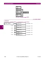
FLEXELEMENT 1 PICKUP
setting specifies the operating threshold for the effective operating signal of the element. If set
to “Over”, the element picks up when the operating signal exceeds the
FLEXELEMENT 1 PICKUP
value. If set to “Under”, the
element picks up when the operating signal falls below the
FLEXELEMENT 1 PICKUP
value.
The
FLEXELEMENT 1 HYSTERESIS
setting controls the element dropout. It should be noticed that both the operating signal
and the pickup threshold can be negative facilitating applications such as reverse power alarm protection. The FlexElement
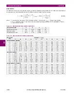
can be programmed to work with all analog actual values measured by the relay. The
FLEXELEMENT 1 PICKUP
setting is
entered in per-unit values using the following definitions of the base units:
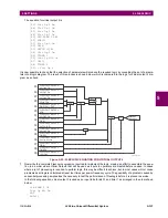
The
FLEXELEMENT 1 HYSTERESIS
setting defines the pickup–dropout relation of the element by specifying the width of the
hysteresis loop as a percentage of the pickup value as shown in the
FlexElement direction, pickup, and hysteresis
diagram.
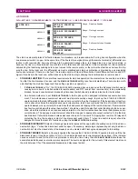
The
FLEXELEMENT 1 DT UNIT
setting specifies the time unit for the setting
FLEXELEMENT 1 dt
. This setting is applicable only if
FLEXELEMENT 1 COMP MODE
is set to “Delta”. The
FLEXELEMENT 1 DT
setting specifies duration of the time interval for the
rate of change mode of operation. This setting is applicable only if
FLEXELEMENT 1 COMP MODE
is set to “Delta”.
This
FLEXELEMENT 1 PKP DELAY
setting specifies the pickup delay of the element. The
FLEXELEMENT 1 RST DELAY
setting
specifies the reset delay of the element.
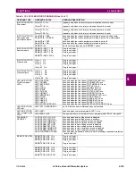
Table 5–13: FLEXELEMENT BASE UNITS
87L SIGNALS
(Local IA Mag, IB, and IC)
(Diff Curr IA Mag, IB, and IC)
(Terminal 1 IA Mag, IB, and IC)
(Terminal 2 IA Mag, IB and IC)
I
BASE
= maximum primary RMS value of the +IN and –IN inputs
(CT primary for source currents, and 87L source primary current for line differential currents)
87L SIGNALS
(Op Square Curr IA, IB, and IC)
(Rest Square Curr IA, IB, and IC)
BASE = Squared CT secondary of the 87L source
BREAKER ARCING AMPS
(Brk X Arc Amp A, B, and C)
BASE = 2000 kA
2
cycle
dcmA
BASE = maximum value of the
DCMA INPUT MAX
setting for the two transducers configured
under the +IN and –IN inputs.
DELTA TIME
BASE = 1 µs
FREQUENCY
f
BASE
= 1 Hz
PHASE ANGLE
BASE
= 360 degrees (see the UR angle referencing convention)
POWER FACTOR
PF
BASE
= 1.00
RTDs
BASE = 100°C
SOURCE CURRENT
I
BASE
= maximum nominal primary RMS value of the +IN and –IN inputs
SOURCE POWER
P
BASE
= maximum value of V
BASE
I
BASE
for the +IN and –IN inputs
SOURCE VOLTAGE
V
BASE
= maximum nominal primary RMS value of the +IN and –IN inputs
SYNCHROCHECK
(Max Delta Volts)
V
BASE
= maximum primary RMS value of all the sources related to the +IN and –IN inputs
Содержание L30
Страница 10: ...x L30 Line Current Differential System GE Multilin TABLE OF CONTENTS ...
Страница 30: ...1 20 L30 Line Current Differential System GE Multilin 1 5 USING THE RELAY 1 GETTING STARTED 1 ...
Страница 58: ...2 28 L30 Line Current Differential System GE Multilin 2 4 SPECIFICATIONS 2 PRODUCT DESCRIPTION 2 ...
Страница 126: ...4 30 L30 Line Current Differential System GE Multilin 4 3 FACEPLATE INTERFACE 4 HUMAN INTERFACES 4 ...
Страница 370: ...5 244 L30 Line Current Differential System GE Multilin 5 10 TESTING 5 SETTINGS 5 ...
Страница 396: ...6 26 L30 Line Current Differential System GE Multilin 6 5 PRODUCT INFORMATION 6 ACTUAL VALUES 6 ...
Страница 450: ...10 10 L30 Line Current Differential System GE Multilin 10 4 INSTANTANEOUS ELEMENTS 10 APPLICATION OF SETTINGS 10 ...
Страница 464: ...A 10 L30 Line Current Differential System GE Multilin A 1 PARAMETER LISTS APPENDIX A A ...
Страница 600: ...C 30 L30 Line Current Differential System GE Multilin C 7 LOGICAL NODES APPENDIX C C ...
Страница 610: ...D 10 L30 Line Current Differential System GE Multilin D 1 IEC 60870 5 104 APPENDIX D D ...
Страница 622: ...E 12 L30 Line Current Differential System GE Multilin E 2 DNP POINT LISTS APPENDIX E E ...
Страница 634: ...F 12 L30 Line Current Differential System GE Multilin F 3 WARRANTY APPENDIX F F ...
Страница 644: ...x L30 Line Current Differential System GE Multilin INDEX ...