


8-2
B90 Low Impedance Bus Differential System
GE Multilin
8.2 DYNAMIC BUS REPLICA
8 THEORY OF OPERATION
8
8.2DYNAMIC BUS REPLICA
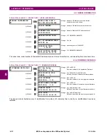
8.2.1 DYNAMIC BUS REPLICA MECHANISM
The bus differential zones of the B90 allow for protecting bus sections that include circuits that are switchable between dif-
ferent sections. Proper relay operation is achieved by associating a status signal with each input current. This mechanism
is referred to as a dynamic bus replica.
The dynamic bus zone is programmed as a number of
CT input–status–direction
entries.
The status signal of a given
CT input–status
pair of the dynamic bus replica is a FlexLogic operand created to indicate
whether or not the associated circuit (current) is connected to the protected bus zone. Normally, the status signals are to be
created from input contacts wired to appropriate auxiliary contacts of isolator switches or breakers.
8.2.2 CT RATIO MATCHING
The B90 allows for using CTs with various rated secondary currents and transformation ratios. Scaling to a common base is
performed internally by the relay. The maximum allowable ratio mismatch is 32:1. For proper setting of the differential char-
acteristic, it is imperative to understand the common base used by the relay.
The B90 scales the secondary currents to the maximum primary current among the CTs defining a given bus differential
zone: 1 per unit corresponds to the highest rated primary current.
The scaling base is selected automatically by the relay during the configuration phase and is not affected by the dynamic
aspect of the bus differential zone. This means that even though the circuit containing the CT with the maximum rated pri-
mary current is not connected to a given bus zone at a given time, the scaling base does not change.
EXAMPLE 2:
Assume the CTs installed in the circuit defining the BUS ZONE 1 have the following ratings:
•
1A CT: 600:5
•
1B CT: 500:1
•
1C CT: 600:5
•
1D CT: 1000:5
•
1E CT: 500:1
•
1F CT: 600:5
The maximum of 600, 500, 600, 1000, 500, and 600 is 1000 A which is therefore selected as the base upon configuration
of the BUS ZONE 1. 1 per unit (pu) represents 1000A primary.
Содержание B90
Страница 10: ...x B90 Low Impedance Bus Differential System GE Multilin TABLE OF CONTENTS ...
Страница 50: ...2 20 B90 Low Impedance Bus Differential System GE Multilin 2 3 SPECIFICATIONS 2 PRODUCT DESCRIPTION 2 ...
Страница 118: ...4 28 B90 Low Impedance Bus Differential System GE Multilin 4 3 FACEPLATE INTERFACE 4 HUMAN INTERFACES 4 ...
Страница 284: ...5 166 B90 Low Impedance Bus Differential System GE Multilin 5 8 TESTING 5 SETTINGS 5 ...
Страница 334: ...10 8 B90 Low Impedance Bus Differential System GE Multilin 10 2 BATTERIES 10 MAINTENANCE 10 ...
Страница 338: ...A 4 B90 Low Impedance Bus Differential System GE Multilin A 1 PARAMETER LISTS APPENDIX A A ...
Страница 460: ...C 30 B90 Low Impedance Bus Differential System GE Multilin C 7 LOGICAL NODES APPENDIX C C ...
Страница 476: ...E 10 B90 Low Impedance Bus Differential System GE Multilin E 1 IEC 60870 5 104 APPENDIX E E ...
Страница 502: ...viii B90 Low Impedance Bus Differential System GE Multilin INDEX ...