


GE Multilin
B90 Low Impedance Bus Differential System
5-89
5 SETTINGS
5.3 SYSTEM SETUP
5
5.3SYSTEM SETUP
5.3.1 AC INPUTS
a) CURRENT TERMINALS
PATH: SETTINGS
SYSTEM SETUP
AC INPUTS
CURRENT TERMINAL F1(S8)
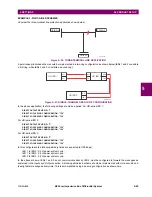
This menu configures the AC current inputs. Upon power up, the B90 recognizes all the AC modules loaded in its chassis
and populates the above menu accordingly.
The current terminals are denoted in the following format:
Xa
, where
X
= {
F
,
L
,
S
} and
a
= (
1
,
2
,...,
8
}.
X
represents the
chassis slot containing the AC input module and
a
represents the AC channel of each module. For example, a B90 unit
containing the F8H and L8K modules displays the following current inputs for configuration: F1, F2, F3, F4, F5, F6, F7, F8,
L1, L2, L3, L4, L5, L6, and L7.
b) VOLTAGE TERMINALS
PATH: SETTINGS
SYSTEM SETUP
AC INPUTS
VOLTAGE TERMINAL F1(S8)
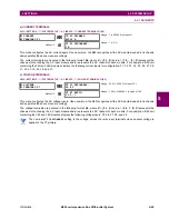
This menu configures the AC voltage inputs. Upon power up, the B90 recognizes all the AC modules loaded in its chassis
and populates the above menu accordingly.
The voltage terminals are denoted in the following format:
Xa
, where
X
= {
F
,
L
,
S
} and
a
= (
5
,
6
,
7
,
8
}.
X
represents the
chassis slot containing the AC input module and
a
represents the AC channel of each module. For example, a B90 unit
containing the F8F and L8K modules displays the following voltage inputs: F5, F6, F7, F8, and L8.
The nominal
VT F1 SECONDARY
setting is the voltage across the relay input terminals when nominal voltage is
applied to the VT primary.
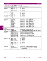
CURRENT
TERMINAL F1
CT F1 PRIMARY:
65000 A
Range: 1 to 65000 A in steps of 1
MESSAGE
CT F1 SECONDARY:
1 A
Range: 1 A, 5 A
VOLTAGE
TERMINAL F1
VT F1 SECONDARY:
66.4 V
Range: 50.0 to 240.0 V in steps of 0.1
MESSAGE
VT F1 RATIO:
1.00 :1
Range: 1.00 to 24000.00 :1 in steps of 1.00
NOTE
Содержание B90
Страница 10: ...x B90 Low Impedance Bus Differential System GE Multilin TABLE OF CONTENTS ...
Страница 50: ...2 20 B90 Low Impedance Bus Differential System GE Multilin 2 3 SPECIFICATIONS 2 PRODUCT DESCRIPTION 2 ...
Страница 118: ...4 28 B90 Low Impedance Bus Differential System GE Multilin 4 3 FACEPLATE INTERFACE 4 HUMAN INTERFACES 4 ...
Страница 284: ...5 166 B90 Low Impedance Bus Differential System GE Multilin 5 8 TESTING 5 SETTINGS 5 ...
Страница 334: ...10 8 B90 Low Impedance Bus Differential System GE Multilin 10 2 BATTERIES 10 MAINTENANCE 10 ...
Страница 338: ...A 4 B90 Low Impedance Bus Differential System GE Multilin A 1 PARAMETER LISTS APPENDIX A A ...
Страница 460: ...C 30 B90 Low Impedance Bus Differential System GE Multilin C 7 LOGICAL NODES APPENDIX C C ...
Страница 476: ...E 10 B90 Low Impedance Bus Differential System GE Multilin E 1 IEC 60870 5 104 APPENDIX E E ...
Страница 502: ...viii B90 Low Impedance Bus Differential System GE Multilin INDEX ...