


5-28
B90 Low Impedance Bus Differential System
GE Multilin
5.2 PRODUCT SETUP
5 SETTINGS
5
The purpose of the Far-End Fault feature is to allow the stations on both ends of a pair of fibers to be informed when there
is a problem with one of the fibers. Without the Far-End Fault feature, it is impossible for a fiber interface to detect a prob-
lem that affects only its transmit fiber.
When the Far-End Fault feature is supported, a loss of receive signal (link) causes the transmitter to generate a Far-End
Fault pattern in order to inform the device at the far end of the fiber pair that a fault has occurred.
When the local receiver again detects a signal, the local transmitter automatically returns to normal operation.
If a Far-End Fault pattern is received by a fiber interface that supports the Far-End Fault feature and it is enabled, it reacts
by dropping the link as if there were no signal at all.
If the receiving interface does not support the Far-End Fault feature or has it disabled, an incoming Far-End Fault pattern is
ignored.
It is strongly recommended to have switches used at substation automation support the Far-End Fault feature, especially
when UR 7 redundancy Failover is selected for redundancy purpose.
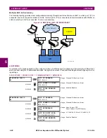
f) PARALLEL REDUNDANCY PROTOCOL (PRP)
The Parallel Redundancy Protocol (PRP) defines a redundancy protocol for high availability in substation automation net-
works. It applies to networks based on Ethernet technology (ISO/IEC 8802-3) and is based on the second edition (July
2012) of the IEC 62439-3, clause 4.
PRP is designed to provide seamless recovery in case of a single failure in the network, by using a combination of LAN
duplication and frame duplication technique. Identical frames are sent on two completely independent networks that con-
nect source and destination. Under normal circumstances both frames reach the destination and one of them is sent up the
OSI stack to the destination application, while the second one is discarded. If an error occurs in one of the networks and
traffic is prevented from flowing on that path, connectivity is still provided through the other network to ensure continuous
communication. Take care when designing the two LANs, so that no single point of failure (such as a common power sup-
ply) is encountered, as such scenarios can bring down both LANs simultaneously.
Figure 5–7: EXAMPLE OF PARALLEL REDUNDANT NETWORK
PRP uses specialized nodes called doubly attached nodes (DANPs) for handling the duplicated frames. DANPs devices
have an additional module, called Link Redundancy Entity (LRE). LRE is responsible for duplicating frames and adding the
specific PRP trailer when sending the frames out on the LAN, as well as making decisions on received frames as to which
one is sent up the OSI stack to the application layer and which one is discarded. LRE is responsible for making PRP trans-
parent to the higher layers of the stack. There is a second type of specialized device used in PRP networks, called RedBox,
with the role of connecting Single Attached Nodes (SANs) to a redundant network.
UR relays implement only the DANP functionality. The RedBox functionality is not implemented.
The original standard IEC 62439-3 (2010) was amended to align PRP with the High-availability Seamless Redundancy
(HSR) protocol. To achieve this, the original PRP was modified at the cost of losing compatibility with the PRP 2010 ver-
sion. The revised standard IEC 62439-3 (2012) is commonly referred to as PRP-1, while the original standard is PRP-0.
The UR relays support only PRP-1.
The relay implements PRP on two of its Ethernet ports, specifically Port 2 and 3 of the CPU module. Use the previous sec-
tion (network port configuration) to configure PRP.
Содержание B90
Страница 10: ...x B90 Low Impedance Bus Differential System GE Multilin TABLE OF CONTENTS ...
Страница 50: ...2 20 B90 Low Impedance Bus Differential System GE Multilin 2 3 SPECIFICATIONS 2 PRODUCT DESCRIPTION 2 ...
Страница 118: ...4 28 B90 Low Impedance Bus Differential System GE Multilin 4 3 FACEPLATE INTERFACE 4 HUMAN INTERFACES 4 ...
Страница 284: ...5 166 B90 Low Impedance Bus Differential System GE Multilin 5 8 TESTING 5 SETTINGS 5 ...
Страница 334: ...10 8 B90 Low Impedance Bus Differential System GE Multilin 10 2 BATTERIES 10 MAINTENANCE 10 ...
Страница 338: ...A 4 B90 Low Impedance Bus Differential System GE Multilin A 1 PARAMETER LISTS APPENDIX A A ...
Страница 460: ...C 30 B90 Low Impedance Bus Differential System GE Multilin C 7 LOGICAL NODES APPENDIX C C ...
Страница 476: ...E 10 B90 Low Impedance Bus Differential System GE Multilin E 1 IEC 60870 5 104 APPENDIX E E ...
Страница 502: ...viii B90 Low Impedance Bus Differential System GE Multilin INDEX ...