GA-02.029-EN-03-05-2018 gAVC 1200 Installation Manual.docx
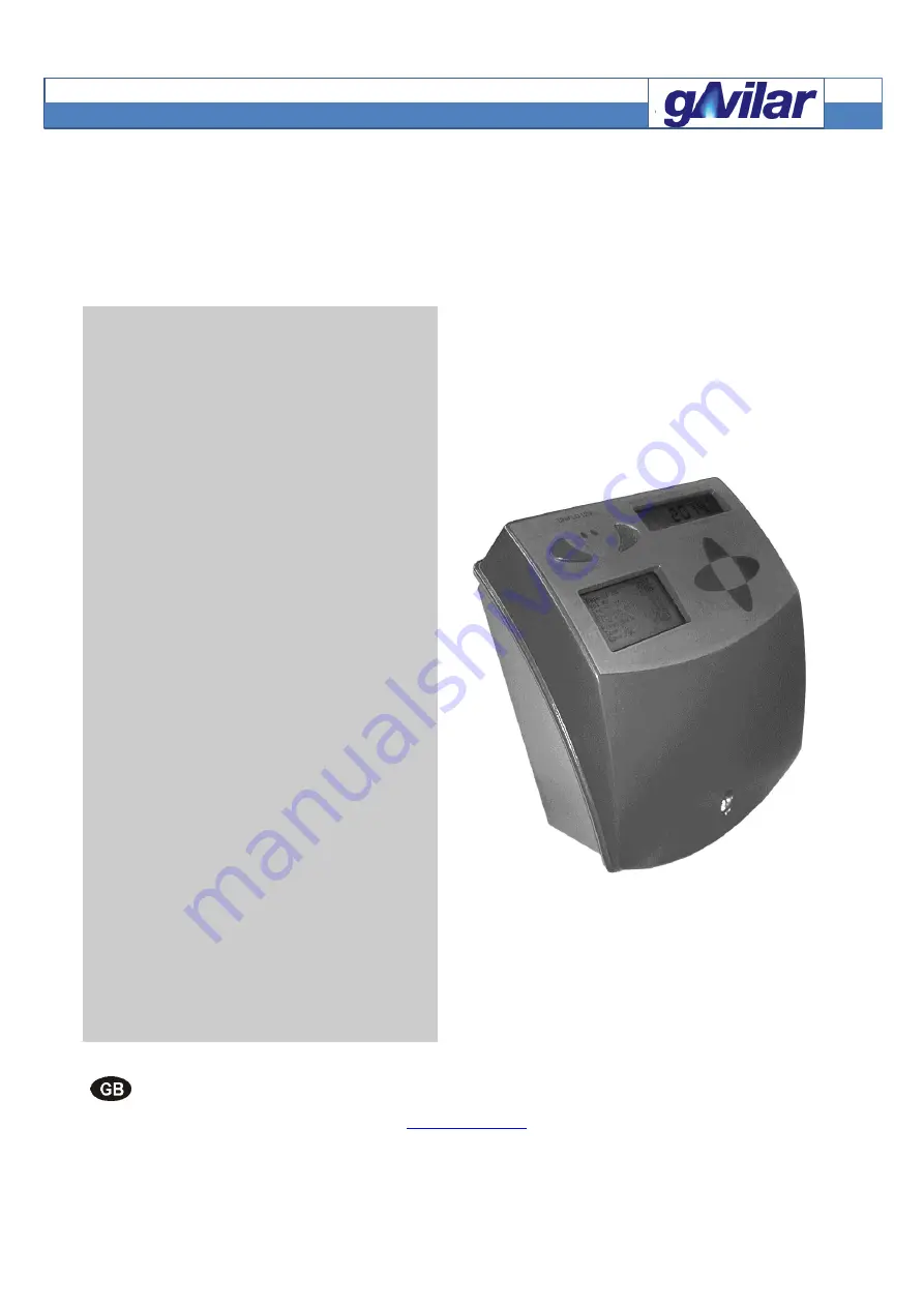
gAVC 1200 N and gAVC 1200 NP
Gas Volume Converter
Installation Manual
GA-02.029-EN-03-05-2018
Rev. 03
Please look at our homepage
www.gavilar.nl
for the latest version of the
document.
Страница 1: ...018 gAVC 1200 Installation Manual docx gAVC 1200 N and gAVC 1200 NP Gas Volume Converter Installation Manual GA 02 029 EN 03 05 2018 Rev 03 Please look at our homepage www gavilar nl for the latest version of the document ...
Страница 2: ...ge 2 of 31 gAVC 1200 N and gAVC 1200 NP overview Metrologic seal Metrologic seal Battery Cable glands Cable mounting brackets Terminals Option board connection bar Power supply DIP switches hardware password setting Standard display Keypad 4 scrolling buttons IR interface Graphic display Label ...
Страница 3: ...14 4 7 Alarm inputs 15 4 8 Alarm output 15 4 9 IR interface Permanent Remote Reading connection 16 5 0 Ex installation ATEX SCHEDULED 17 5 1 General considerations 17 5 2 Installation inspection and maintenance in hazardous environment 17 5 3 Pressure and temperature sensor cables 18 5 4 Pulse and alarm outputs 18 5 5 Uniwire 18 5 6 Earthing and connection of conducting cable screens 19 5 7 Cable ...
Страница 4: ...AVC 1200 Installation Manual docx GA 02 029 EN 03 05 2018 rev 03 Page 4 of 31 8 4 Temperature sensor 28 8 5 Inputs and outputs 29 8 5 Communication 30 9 0 Applicable standards 30 10 0 Disposal of the product after end of use 30 ...
Страница 5: ...ion board in the gAVC 1200 N will degrade the zone from 0 to 1 The ATEX identification will change from Ga to Gb 1 2 Operating principle gAVC 1200 N NP records all volume pulses that is received from the gas meter If any pulses are registered the temperature and pressure are measured After this the system makes a correction calculation and an energy calculation consequently updating all parameters...
Страница 6: ...0 temperature sensor with 3 m cable C Optional gAVC Configuration Program gAVC Config Pressure sensor housing Dimensions ø25 mm Length 103 5 mm Temperature sensor pocket Dimensions ø5 mm Length 50 mm A wide range of option boards 1 4 Definitions Technicians are qualified persons educated or trained to mount operate and also troubleshoot technically correct and in accordance with safety regulations...
Страница 7: ...arate package with separate manuals 2 2 At delivery The gAVC 1200 N NP system is delivered fully mounted with temperature and pressure sensor ready to install Only if the installation requires more features such as connection of inputs outputs additional programming etc it is necessary to tamper with the unit 2 3 gAVC Config A special software program is developed for setting up and reading of the...
Страница 8: ...ption boards Screw driver Slotted Parallel tip 5 mm Enclosure screw Cabinet mounting screw Screw driver Slotted Parallel tip 2 mm Small screw terminal Screw driver Torx T 8 Option board cable glands Screw driver Torx T 10 All other Torx screws Long nose pliers Useful when mounting wires 4 0 Installation General The gAVC unit must be installed according to local regulations for installation in haza...
Страница 9: ... the mounting bracket and sealing plate At delivery the mounting bracket and sealing plate is factory mounted All that remains to be done is to mount 2 screws on the wall 1 Mount the 2 screws on the wall 2 Place the gAVC unit on the screws the keyholes in the mounting bracket Mounting bracket Mounted on delivery Sealing plate Option Internal mounting screw 3 Pull the unit downwards until it clicks...
Страница 10: ... connections Pulse output 1 2 Pressure sensor A B 1 White 2 Blue 3 Yellow 4 Red 5 Black 6 Green blue cable Orange black cable GND not used Alarm input alarm when alarm circuit is open Pulse input b INb GND Pulse input a Ina GND Temperature sensor XP5 XP4 XP3 XP2 XP1 The cables are tightened in the cable glands It is important when using shielded cable that the shield is securely connected to the c...
Страница 11: ...al data Green blue cable Orange black cable Pressure sensor GND Not used Cable gland Pressure sensor screen Screen Temp sensor A Pt 1000 temperature sensor Pemp sensor B Pt 1000 temperature sensor Pulse and alarm inputs Ina LF pulse input a Inb LF pulse input b IN Alarm input GND GND Pulse and alarm outputs serial communication Pulse 1 out Pulse output 1 positive Pulse 1 out Pulse output 1 negativ...
Страница 12: ... Hard cables HSPS 0 6 mmØ winded pairs shielded Shielded cables suitable for measurement Screw terminals and wire dimensions Terninals Stranded wire Max cross section mm2 Stranded wire Min cross section mm2 Solid wire Max cross section mm2 Solid wire Min cross section mm2 Earth 1 5 0 14 2 5 0 14 pulse alarm and serial outputs 2 5 0 14 4 5 0 14 pulse and alarm inputs 1 0 14 1 5 0 14 Option boards c...
Страница 13: ...lation data Temperature index Then the system will detect the correct settings When the temperature sensor is installed in the sensor pocket it must be sealed with a wire Sensor pocket mounting Seal Sensor Sensor pocket 4 4 Pressure sensor The pressure sensor is mounted in the gAVC unit by gAvilar when delivered The pressure sensor is installed in the pressure tap either at the meter or at the inl...
Страница 14: ... to 1 2VDC PS 3 6VDC Max Pulse frequency 3 Hz Fastest On time 33 m sec Fastest Off time 300 m sec Max On resistance 1 Kohm LTL 0 7 V VCC 3 6 V Rpull up 43 K 3 Hz Max Off resistance 4 Mohm UTL 2 9 V VCC 3 6 V Rpull up 470 K 3 Hz Configuration The pulse inputs are configured in gAVC Config 4 6 Pulse outputs There are 2 pulse outputs on the gAVC 1200 N NP The outputs can be used to repeat the convert...
Страница 15: ...se 2 Output Alarm Output Serial PA EEx Earth A B Pulse input Alarm input Alarm input IN GND When the Tamper alarm is activated the word alarm in the gAVC display will appear if set up in gAVC Config The word alarm will disappear when the alarm disappears if set up in gAVC Config 4 8 Alarm output The alarm output may be connected to an external alarm input Current alarms As long as the origin of th...
Страница 16: ...e Reading connection The gAVC 1200 N NP and the gAVC Config may be connected in 2 ways Via the IR interface The IR interface is attached to the gAVC unit with the built in magnets Permanently via the serial link Programming via IR interface Programming via serial link Connected to the computer com port Connected to the computer com port ...
Страница 17: ...ds of tree earth connection for zone 0 equipment See section 5 6 of this manual 5 1 General considerations Only technicians who are familiar with the technical terms warnings and instructions in the manual and who are able to follow these should connect the module Should there be any doubt as to the correct handling of the module please contact your local distributor or alternatively gAvilar b v K...
Страница 18: ...P4 and XP5 The three outputs are electrically identical Ex data Uin 28V Iin 75mA Pin 0 55W Cin 57 nF Lin negligibly small As zener barrier may be used a Pepperl Fuchs type Z728 5 5 Uniwire This terminal is marked XP2 Ex data This is part of the Ex Data at 5 4 As Zener barrier you may use a Pepperl Fuchs type Bi polare Z966 AC Uni polare Z722 DC Check the earth connection of the connected equipment...
Страница 19: ...crew terminal marked GND in the section for pressure sensor gAVC and gas pipe meter may have to be connected with an earth connection depending on actual installation conditions Precautions must be taken to avoid static electricity Do not mount gAVC on electrically isolated base At mounting the gAVC First connect the earth wires and then the rest of wires afterwards At dismounting the gAVC Keep on...
Страница 20: ...components in the gAVC 1200 Therefore it s of outmost importance that the operator follows these instructions Remove old battery Actual data was stored when the cabinet was opened Insert new battery please observe ESD correct mounting Only batteries approved by gAvilar Attention Use the right battery gAVC 1200 N for main battery supply marked TÜV 18 ATEX 220433 X use 94128 gAVC 1200 NP with extern...
Страница 21: ...ATEX marking is placed on the left or right side of the bottom part The markings are as follows Battery power gAVC Battery powered gAVC with Externally powered gAVC with option boards Back up battery and with or without option boards Pulse option board part of TÜV18 ATEX 220433X Battery label for gAVC 1200 N Battery label for gAVC 1200 NP ...
Страница 22: ...ts 5 10 Option boards The option boards which can be used in the gAVC are ATEX approved by TÜV with Certificate number TÜV 17 ATEX 211195 X ATEX relevant information for option boards is to be found in their individual installation manuals This includes information about marking EX data for input and output conditions for safe use zone classes and categories Be aware of that some option boards nee...
Страница 23: ...missioning 6 1 Sealing If there has been performed any installation on the unit breaking of the outer seal the entire system must be sealed in the correct way gAVC 1200 N NP Main metrologic seal Sealing hole Sealing screw have to be screwed down with a torque on 1 5Nm Temperature sensor Seal Sensor Sensor pocket ...
Страница 24: ...on Temperature and pressure sensor terminals The temperature and pressure sensor terminals are secured with sealing tape on delivery Hardware password DIP switches The hardware DIP switches are secured with sealing tape on delivery For setting combination please refer to Functional Description 6 2 Programmed in factory The gAVC unit is programmed in compliance with the order and may be taken into ...
Страница 25: ... and when it reaches 90 days 10 remaining capacity the Low battery warning is activated Non standard autonomy time For batteries gAvilar units that are installed in an environment that deviates from the reference conditions such as very low or high temperature short measurement intervals etc these parameters may change and has to be taken into consideration When the battery has been replaced remem...
Страница 26: ...stallation Manual docx GA 02 029 EN 03 05 2018 rev 03 Page 26 of 31 8 0 Technical data 8 1 Dimensions gAVC 1200 N NP 75 mm 201 mm 101 9 mm Incl Mounting bracket 160 mm 100 mm 4 mm 110 mm 75 mm 90 mm Temperature sensor 50 mm 1500 mm 50 mm ...
Страница 27: ... 05 2018 gAVC 1200 Installation Manual docx GA 02 029 EN 03 05 2018 rev 03 Page 27 of 31 90 mm 6 mm 15 mm G or NPT 12 mm Sealing screw Pressure sensor 15 5 64 0 94 0 Process G 1 4 female ø1 for sealing NV 22 ø 25 ø 6 ...
Страница 28: ...a IIB T3 Alarm 14 pcs 4 7 mm standard 7 pcs 7 blinds Pulse output Alarm output 2 LF inputs compare function Serial ports 1 input e g tamper switch 2 configurable 1 1 optical EN 62056 1 fixed 2 wire half duplex 1 optical fibre option all MODBUS RTU 8 3 Pressure sensor Pressure sensor Cable Ø6 mm length 3m Pressure ranges 2 barA 6 barA 14 barA 30 barA 80 barA Accuracy 0 2 R at ambient temperature 20...
Страница 29: ...C Low trigger level 0 7 to 1 8VDC PS 3 6VDC Hysteresis 0 3 to 1 2VDC PS 3 6VDC Max Pulse frequency 3 Hz Fastest On time 33 m sec Fastest Off time 300 m sec Max On resistance 1 Kohm LTL 0 7 V VCC 3 6 V Rpull up 43 K 3 Hz Max Off resistance 4 Mohm UTL 2 9 V VCC 3 6 V Rpull up 470 K 3 Hz Alarm input Pull up resistor 1 Mohm RC filter 10K 100nF Delay when open 100 msec Delay when closed 1 mSec Current ...
Страница 30: ...ent when idle power supply 5V 100 A Transmit current transmitter on Nominal 5 mA Receiver Receiver on current Min 1 5 mA Impedance 1 9 Kohm On current at 5V 2 6 mA Maximum data Power 300 mW Current 50 mA 9 0 Applicable standards EN 60079 0 2012 A11 Explosive atmospheres part 0 General equipment EN 60079 11 2012 Explosive atmospheres part 11 equipment protected by intrinsic safety i 10 0 Disposal o...
Страница 31: ...Ex Installation is ATEX scheduled Rev Init Comment 03 05 2018 EvdV Document created 20 06 2018 EvdV Model modification ATEX information changed gAvilar b v Kamerlingh Onnesweg 63 Dordrecht The Netherlands Tel 31 85489 7130 E mail info gavilar nl Flonidan Gas Division A S Islandsvej 29 DK 8700 Horsens Tel 45 75618888 Fax 45 75626088 E mail mail flonidan dk ...