Reference Data 111
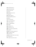
I/O map
The following table gives descriptions of what the memory is used for at
each address location.
Address
(hex)
Size
Description
0000–000F
16 bytes
DMA-1
0020–0021
2 bytes
INT-1
0040
1 byte
Programmable interval timer 1
0041
1 byte
Refresh request counter 1
0042
1 byte
Speaker tone counter 2
0043
1 byte
Command mode register
0048
1 byte
Programmable interval timer 2
0049
1 byte
Reserved
004A
1 byte
CPU speed control counter 2
004B
1 byte
Command mode register
0061-0070
16 bytes
NMI status/registers
0080-008F
16 bytes
DMA page registers
00A0-00A1
2 bytes
INT-2
00C0-00DE
31 bytes
DMA2
0400-040F
16 bytes
DMA1
0461-0464
4 bytes
Extended NMI control
0480-048F
16 bytes
DMA high page register
04C2
1 byte
Reserved
04C6-04CE
8 bytes
DMA2
04D0-04DF
16 bytes
INT/DMA2
04E0-04FF
32 bytes
DMA
4075.book Page 111 Friday, April 2, 1999 9:26 AM
Содержание ALR 7300
Страница 34: ...24 Maintaining and Troubleshooting the Gateway ALR 7300 Server 4075 book Page 24 Friday April 2 1999 9 26 AM...
Страница 70: ...60 Maintaining and Troubleshooting the Gateway ALR 7300 Server 4075 book Page 60 Friday April 2 1999 9 26 AM...
Страница 92: ...82 Maintaining and Troubleshooting the Gateway ALR 7300 Server 4075 book Page 82 Friday April 2 1999 9 26 AM...


