background image

Velox to G-Shield Fire Upgrade Kit Instructions

14

Version 3

P/N 761011-02

14. Wiring Diagram

Use stranded tinned copper conductors in a PVC jacket. Cable size of 16 AWG to 22 AWG is 

suitable. The maximum allowable outside diameter (OD) is 6.5 mm. Use insulated bootlace 

ferrules to avoid damage to the copper conductors.

15. Cable Information

Use four core sheathed cable between the touchscreen and the Sensor Platforms. The 

maximum cable length permitted is 20 m.

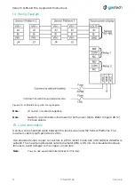
You can use equivalent alternatives for this item.

Note: 

Figure 26. G-Shield Fire system wiring diagram.

J3 and J4  are interchangeable.

Note: 

Gastech recommends inline fuses for both power feeds. Refer to figure 26 for 

the fuse values.

Note: 

Содержание G-SHIELD-FIRE

Страница 1: ...ech com HEAD OFFICE 24 Baretta Road Wangara WA 6065 Phone 61 8 6108 0000 SYDNEY OFFICE Suite G01 10 Tilley Lane Frenchs Forest NSW 2086 Phone 61 2 9451 0054 BRISBANE OFFICE PO Box 349 Cannon Hill Qld...

Страница 2: ...connected to touchscreen 6 Figure 9 Touchscreen DisplayDeviceUtility connected devices screen 6 Figure 10 Touchscreen upgrade device software screen 7 Figure 11 Select software for touchscreen device...

Страница 3: ...on guide Software Download directly from https gastech com g shieldfire 1 3 mm hex wrench for Bushing Nut grubscrew WARNING The G Shield Fire must be installed by an approved person Incorrect installa...

Страница 4: ...these obsolete parts to Gastech for responsible disposal Figure 1 Velox Sensor Head image Figure 2 Velox Sensor Bushing image Figure 3 Velox Touchscreen PCBA image The removal of the Velox system is n...

Страница 5: ...than the other Small movements are best The PCBA must be removed without excessive force to avoid damage to the touchscreen connector pins CAUTION Figure 4 G Shield Fire Touchscreen PCBA image Figure...

Страница 6: ...DeviceUtility connected devices screen Download the Velox to G Shield Fire Upgrade Kit software from https gastech com g shieldfire Select the downloads tab and choose the file 84 1011 01 Software Pac...

Страница 7: ...reen device software Select the Upgrade Device Software menu Figure 10 Touchscreen upgrade device software screen Figure 11 Select software for touchscreen device upgrade screen Step 1 Step 1 Select t...

Страница 8: ...e 12 Touchscreen software update start screen Figure 13 Touchscreen software update under way Figure 14 Touchscreen device software update completed Reboot required Double click on the device software...

Страница 9: ...ftware Figure 15 G Shield Fire application upload screen Figure 16 G Shield Fire application file selection Figure 17 G Shield Fire application upload start screen Select the Upload project menu Step...

Страница 10: ...will automatically reboot to complete installation Note Figure 18 G Shield Fire application upload started Figure 19 G Shield Fire application upload completed Reboot required Install the G Shield Fir...

Страница 11: ...grade Kit Instructions 11 Version 3 P N 761011 02 10 Attach the G Shield Fire PCBA to the Touchscreen Step 1 Fit the PCBA to the touchscreen Do not bend any pins on the touchscreen Figure 20 Attach th...

Страница 12: ...Splash Guard protects the G Pod from wind and water to the ingress protection level IPX6 and must always be fitted CAUTION Figure 21 Sensor Platform exploded diagram Install the Sensor Platforms vert...

Страница 13: ...G Pod CAUTION Figure 23 G Pod key Figure 24 Sensor Platform keyway Figure 25 Sensor Platform Bushing Nut Align the key on the G Pod with the keyway on the Sensor Platform Push the G Pod into the Senso...

Страница 14: ...insulated bootlace ferrules to avoid damage to the copper conductors 15 Cable Information Use four core sheathed cable between the touchscreen and the Sensor Platforms The maximum cable length permit...

Страница 15: ...Connect the vehicle accessories circuit to ACC The touchscreen will turn on and off with the vehicle ignition Connect the vehicle battery input to VBAT The G Shield Fire can be installed into vehicle...

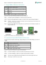
Страница 16: ...rical Connections The touchscreen has two alarm relay outputs Relay 1 can be muted Relay 2 cannot be muted Connect the Relay 2 output to an external visual alarm indicator The relays are activated whe...

Страница 17: ...ervice marks of GasTech Australia Pty Ltd The use of the symbol indicates registration in the United States and the indicates registration in Australia Registrations may not have been issued at presen...

Отзывы: