|
21
Types of Machines
Machines 305, 405, 3500 and 4100 are delivered in the following designs:
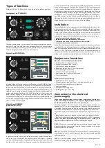
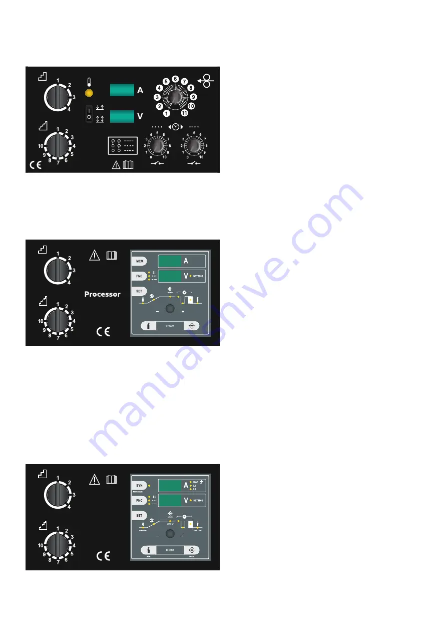
Analogical type STANDARD
Easy and reliable control over machines. Operating is secured by one poten
-
tiometer of wire feed and two other potentiometers with a switch which
controls switching on and setting spot and pulse functions. This type is supp
-
lied with a digital voltampermeter in a standard way.
Digital type PROCESSOR
A simple solution of having control over all functions for MIG/MAG welding.
Simple control and setting of all functions is secured by one potentiome
-
ter and two buttons. Function LOGIC also makes an easy control possible.
Machines with this control are supplied with a digital voltampermeter in a
standard way. A simple solution of having control allows setting values of
pre-gas and post-gas, function SOFT START, burning out of wire, spot and
pulse welding. Regulation allows setting two-time and four-time modes.
Easy advanced feeding of wire to wire feeder. Electronic regulation of speed
of wire feed manages feedback regulation of wire feed which secures con
-
stant set speed of wire shifting.
Digital type SYNERGIC
(except 3500, 4100)
Synergic
It significantly makes setting of welding parameters possible. An operator
sets up the type of a program by using easy setting of diameter of welding
wire and used protective gas. Then you can simply set up voltage when you
use the switch and control unit Synergic chooses the best parameters of
speed of wire feed. Simple operating and setting of all functions is secured
by one potentiometer and two buttons. Function LOGIC also makes an easy
control possible. Machines with this control are supplied with a digital vol
-
tamperme-ter with memory in a standard way. A simple solution of having
control allows setting values of pre-gas and post-gas, function SOFT START,
burning out of wire, spot and pulse welding. Regulation allows setting two
-
-time and four-time modes. Easy advanced feeding of wire to wire feeder.
Electronic regula-tion of speed of wire feed manages feedback regulation of
wire feed which secures constant set speed of wire shifting.
Installation
The installation site for the system must be carefully chosen in order to en
-
sure its satisfactory and safe use. The user is responsible for the installation
and use of the system in accordance with the producer’s instructions con
-
tained in this manual. Before installing the system the user must take into
consideration the potential electromagnetic problems in the work area. In
particular, we suggest that you should avoid installing the system close to:
• signalling, control and telephone cables
• radio and television transmitters and receivers
• computers and control and measurement instruments
• security and protection instruments
Persons fitted with pacemakers, hearing aids and similar equipment must
consult their doctor before going near a machine in operation. The equip
-
ment’s installation environment must comply to the protection level of the
frame i.e. IP 21S. The system is cooled by means of the forced circulation of
air, and must therefore be placed in such a way that the air may be easily
sucked in and expelled through the apertures made in the frame.
Equipment of machines
Machines are also standardly equipped with:
• Earthing cable 3 m long with a grip.
• Hose for gas connection 1.5 m long.
• Cable for gas heating connection.
• Roller for wire of 1.0 and 1.2 mm in diameter.
• Accompanying documentation.
• Reduction for wire 5 kg and 18 kg.
• Replacement fuse for control Electronics.
• 2/4-roll wire feeder.
Special accessories for ordering:
• Welding torch 3, 4 or 5 m long.
• Cylinder pressure regulators for CO
2
or mixed gases of Argon.
• Spare rollers for wires different in diameter.
• 4-roll wire feeder.
• Spare parts of welding torch.
• Earthing cable 4 m or 5 m long.
Connection to the electrical
power supply
Before connecting the welder to the electrical supply check, that the ma
-
chines plate rating corresponds to the supply voltage and frequency and
that the line switch of the welder is in the position „0“.
Use original plug for machines to connect to power supply. Machines are
designed for TN-C-S grid. It’s provided with 5-pin plug. The middle line wire
is not used. Eventual changing of plug can be made only by person with
electrotechnical qualification. If you need to change the plug, follow this:
Connection to the power supply must be carried out using of four polar ca
-
ble:
• three conducting wires, it does not matter, what is the order of phases
• the fourth, yellow-green wire is used for making the „EARTH“ connection
Connect a suitable normalized plug to the power cable. Provide for an
electrical socket complete with fuses or an automatic switch.
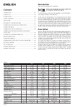
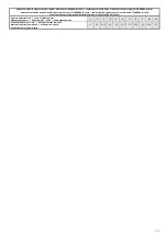
TABLE 2:
Shows the recommended load values for retardant supply fuses
chosen according to the maximum nominal current supplied to the welder
and the nominal supply voltage.
NOTE 1:
Any extensions to the power cable must be of a suitable diameter,
and absolutely not of a smaller diameter than the special cable supplied
with the machine.
NOTE 2:
It is not advisable to plug up the welder to motordriven generators,
as they are known to supply an unstable voltage.
EN
Содержание 305
Страница 22: ... 67 ...


