190-01007-C1
GTN Xi Part 23 AML STC Maintenance Manual
Rev. 1
Page 6-2
6.1 GTN Xi
Removal
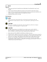
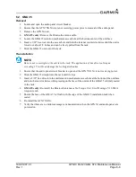
1. Locate and open the GTN Xi GPS/NAV and COM (GTN 635Xi/650Xi/750Xi only) circuit
breakers.
2. Locate the unit retention mechanism access hole at the bottom-left corner of the unit face.
3. Insert a 3/32" hex tool into the access hole and turn the fastener counterclockwise until the unit is
forced out about 3/8 inches and can be freely pulled from the rack.
4. Slide the GTN Xi unit out of the rack.
Re-installation
NOTE
It may be necessary to insert the hex drive tool into the access hole and turn the cam
mechanism 90
°
counterclockwise to ensure correct position prior to placing the unit in the
rack.
CAUTION
Be sure not to overtighten the unit into the rack. The application of hex drive tool torque
exceeding 15 in-lbf can damage the locking mechanism.
CAUTION
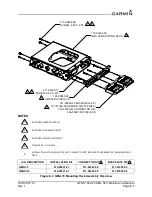
The Bluetooth antenna port on the GMA 35c has a tight clearance from the GTN Xi.
Ensure the GMA 35c and antenna cable are fully seated before inserting the GTN Xi. The
face of the GMA 35c should be flush with the mounting rack when fully seated.
1. Ensure that the GTN Xi GPS/NAV and COM circuit breakers are open.
2. Slide the GTN Xi straight into the rack until it stops about 1 inch short of the fully seated position.
3. Insert a 3/32" hex drive into the unit retention mechanism access hole at the bottom of the unit face
and turn the tool clockwise while pressing the bezel until the unit is firmly seated in the rack.
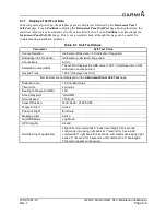
4. Once the unit is re-installed, verify that the unit power-up self-test sequence is successfully
completed and no failure messages or configuration error messages are annunciated. Section 6.1.1
outlines the power-up self-test sequence.
Содержание GTN Xi Series
Страница 42: ......
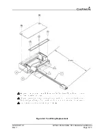
Страница 92: ...190 01007 C1 GTN Xi Part 23 AML STC Maintenance Manual Rev 1 Page 6 17 Figure 6 9 Fan Wiring Replacement...
Страница 163: ......

