background image

5 - PROCEDURES

96

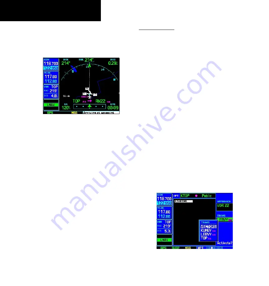
11.  As you approach the MAP, a waypoint alert 

(“Arriving at waypoint”) appears in the lower 
right corner of the screen. CDI scaling continues 

to tighten from 0.3 NM to 350 feet, full-scale 
deflection. 

As you approach the MAP, an  

“Arriving at waypoint” alert appears in the 

lower right corner of the screen. 

12.   As  you  cross  the  MAP,  “SUSP”  appears 

above the 

OBS

 key, indicating that automatic 

sequencing  of  approach  waypoints  is  sus-
pended  at  the  MAP. A “from”  indication  is 
displayed on the CDI and Default NAV Page, 
but course guidance along the final approach 
course continues. Do NOT follow this extended 
course.  Follow  published  missed  approach 
procedures using the 

OBS

 key to initiate the 

missed approach sequence. 

Vectors to Final

Let’s take a second look at the “VOR 22” approach 

into Billard Municipal. Instead of following the DME 
arc, ATC tells you to expect vectors onto the final 
approach course. There are several ways to select “vec-
tors to final” with the 500W-series unit. The first two 
options below normally require the least workload to 
accomplish: 

•  When the approach is first selected, choose “VEC-

TORS” from the transitions (“TRANS”) window.

•  Load a full approach — including the IAF from the 

transitions window. When cleared, press 

PROC


and select “Activate Vectors-To-Final?”. 

•  Load the full approach. Use the 

direct-to

 key (by 

pressing it twice) from the Active Flight Plan Page 
to select the desired leg of the approach. 

To select “VECTORS” from the transitions window: 

1.  Select Billard Muni (KTOP) as your destination, 

using the 

direct-to

 key, or as the last waypoint 

in a flight plan. 

2.  Press the 

PROC

 key and select the “VOR 22” 

approach. 

3.  From  the  transitions  window,  select “VEC-

TORS”. 

Select “VECTORS” from the transitions 

window to activate only the final approach 

course.  

Vectors-To-Final Approach

Содержание GNS 530W

Страница 1: ...500W Series Pilot s Guide Reference...

Страница 2: ...ownloaded or stored in any storage medium for any purpose without the express written permission of Garmin Garmin hereby grants permission to down load a single copy of this manual and of any revision...

Страница 3: ...eive and decode the satellite signals In such event the interference may be reduced or eliminated by switching off the source of interference or moving the GPS receiver away from it CAUTION The electr...

Страница 4: ...t any interference received including interference that may cause undesired operation To obtain accessories for your 500W series please contact your Garmin dealer Help us better support you by complet...

Страница 5: ...nna Installation Rack Connectors Pilot s Guide Quick Reference 400W 500W Series Display Interfaces Addendum 400W 500W Series Garmin Optional Display Interfaces Addendum GNS 400W 500W series Simulator...

Страница 6: ...OR FITNESS FOR A PARTICULAR PURPOSE STATUTORY OR OTHERWISE THIS WARRANTY GIVES YOU SPECIFIC LEGAL RIGHTS WHICH MAY VARY FROM STATE TO STATE IN NO EVENT SHALL GARMIN BE LIABLE FOR ANY INCIDENTAL SPECI...

Страница 7: ...Page Notation 29 Turn Advisory and Waypoint Alert 29 Default NAV Page 30 Selecting Desired On Screen Data 31 Restoring Factory Settings 32 Dual Unit Considerations 32 Default Nav Page Auto Zoom 33 Ma...

Страница 8: ...Flying the Procedure Turn 85 Flying the Missed Approach 88 Flying an Approach with a Hold 89 Flying a DME Arc Approach 93 Vectors to Final 96 Flying the Vectors Approach 97 Course From Fix Flight Plan...

Страница 9: ...lists 170 Trip Statistics 173 RAIM Prediction 173 Software Versions 174 Database Versions 174 Terrain Database Versions 174 Setup 1 Page 175 CDI Alarms 178 Units Position 180 Date Time 181 Display Bac...

Страница 10: ...INTRODUCTION viii Blank Page...

Страница 11: ...the PC based FDE prediction program the GPS 500W may be used for oceanic or remote operations For the latest in graphi cal and textual weather information the GPS 500W can connect to XM Satellite Rad...

Страница 12: ...left knob COM VLOC GNS 530W is used to tune the megahertz MHz value to the left of the decimal point of the standby fre quency for the communications trans ceiver or the VOR Localizer receiver whiche...

Страница 13: ...isplay the Default Navigation Page regardless of the page that is cur rently displayed ENT The enter key ENT is used to approve an operation or complete data entry It is also used to con rm informatio...

Страница 14: ...selector on your HSI or CDI MSG The message key MSG is used to view system messages and to alert you to important warnings and require ments when the MSG annunciator is displayed See Sections 12 and 9...

Страница 15: ...shown here may not exactly match what you see on your 500W series unit Prior to using your 500W series unit for the rst time we recom mend that you taxi to a location that is well away from buildings...

Страница 16: ...lly entered if your installation does not include connection to sensors which automatically provide these gures To enter fuel capacity fuel on board or fuel ow gures if not provided by sensors 1 Turn...

Страница 17: ...execute each step in the selected checklist Select Go To Checklists to display the Checklist Page and any available checklists A 500W series unit can hold up to nine check lists with up to 30 entries...

Страница 18: ...return to the previous page after viewing a message press MSG again The Satellite Status Page shows the ID num bers for the satellites and the relative signal strength of each satellite received as a...

Страница 19: ...tarily to switch the highlight between the COM and VLOC win dows Adjusting the frequencies with the large and small left knobs will affect the standby frequency 2 Turn the large left knob to select th...

Страница 20: ...n Airport Runway Airport Frequency Airport Approach Airport Arrival Airport Departure Intersection NDBs VOR User Waypoint Small right knob to select pages within the group NAV Group Default NAV Map NA...

Страница 21: ...page Press and hold CLR NOTE The number of NAV pages avail able vary depending on the installation of options See 400W 500W Series Dis play Interfaces Pilot s Guide Addendums NRST Group Nearest Airpor...

Страница 22: ...led equipment To select the NAV group and display the Default NAV Page press and hold CLR In addition to the group of NAV pages additional groups of pages are available for waypoint information WPT au...

Страница 23: ...in your ight plan and the nal destination airport When using the direct to function frequencies are listed for the airport nearest to your starting position and the destination airport DEFAULT NAV PA...

Страница 24: ...esired Track To adjust the map scale 1 Press the up arrow on the RNG key to zoom out to a larger area OR 2 Press the down arrow on the RNG key to zoom in to a smaller area By adding data elds along th...

Страница 25: ...ports departure arrival and en route for your ight plan or direct to Continue to turn the small right knob until the desired airport is selected 3 Press ENT to display the frequency list for the selec...

Страница 26: ...ion eld highlighted The direct to waypoint may also be selected by facility or city name See Section 3 for more information 2 Turn the small right knob to enter the rst letter of the destination waypo...

Страница 27: ...s or STARs or departure when using SIDs airport 3 Turn the small right knob to select the desired procedure and press ENT A window appears to select the desired procedure Use the small right knob to m...

Страница 28: ...available under the NRST group Nearest Airport Page Nearest Intersection Page Nearest NDB Page Nearest VOR Page Nearest User Waypoints Page Nearest ARTCC Page Nearest FSS Page Nearest Airspace Page N...

Страница 29: ...emove the cursor and turn the small right knob to display the desired information page The Nearest Airport Page may be used in conjunc tion with the direct to key to quickly set a course to a nearby f...

Страница 30: ...u have entered an airspace the message Inside Airspace appears By default airspace alert messages are turned off When turned on the message MSG annunciator located directly above the MSG key ashes to...

Страница 31: ...rmation about ight plans can be found in the Flight Plan section Section 4 To create a new ight plan 1 Press the FPL key and turn the small right knob to select the Flight Plan Catalog 2 Press the MEN...

Страница 32: ...aces any ight plan which currently exists in ight plan 00 To activate the new ight plan 1 On the Flight Plan Catalog page press the small right knob to activate the cursor Rotate the large right knob...

Страница 33: ...to decrease volume Squelch The COM radio features an automatic squelch to reject many localized noise sources You may override the squelch function by pressing the COM power volume knob This facilita...

Страница 34: ...highlighting the desired frequency on any of the main pages and pressing ENT This pro cess is referred to as auto tuning Once a frequency is selected in the standby eld it may be transferred to the ac...

Страница 35: ...frequency Any COM frequency displayed in the GPS window can be transferred to the standby COM frequency eld with a minimum of keystrokes required The following are some examples of selecting COM frequ...

Страница 36: ...in the standby COM window eld 5 Before leaving the frequency page use the large right knob to highlight Done and press ENT Done always needs to be acknowledged before leaving a page group To select a...

Страница 37: ...COM Page with the frequencies for the selected airport 5 Turn the large right knob to highlight the desired frequency 6 Press ENT to place the highlighted frequency in the standby COM window eld To se...

Страница 38: ...if the com system loses communication with the main system the radio will automatically tune to 121 500 MHz for transmit and receive regardless of the displayed frequency Stuck Microphone Whenever the...

Страница 39: ...lection process convenient to cycle between the Default NAV and Map Pages two of the most frequently used pages Other pages are provided to list frequencies for your ight plan show your current positi...

Страница 40: ...atically adjusts to the desired limits based upon the current phase of ight en route terminal area or approach NOTE Approaching the FAF the GNS 500W series unit automatically rescales in an angular fa...

Страница 41: ...miles To adjust the map range use the RNG key To adjust the map range 1 Press the up arrow on the RNG key to zoom out to a larger area OR 2 Press the down arrow on the RNG key to zoom in to a smaller...

Страница 42: ...to remove the cursor from the page Restoring Factory Settings You can also quickly return all data eld settings to their original factory settings The Restore Defaults option returns all data elds to...

Страница 43: ...s an aid to navigation and is designed to facilitate the use of authorized govern ment charts not replace them Land and water data is provided only as a general reference to your surround ings The pos...

Страница 44: ...distance covered by the map display The map range appears in the lower left corner Use the RNG key to select the desired map range To select a map range 1 Press the up arrow side of the RNG key to zo...

Страница 45: ...yond the boundaries of the current map area without changing the scale Start by pressing the small right knob To select the panning function and pan the map display 1 Press the small right knob to act...

Страница 46: ...ly exists at the crosshair position a new waypoint called MAP is created at the target pointer location before the direct to is initiated Use the panning function and direct to key to select a destina...

Страница 47: ...e arc 2 Press the ENT key to display the Page Menu Highlight Review Airspace 3 Press ENT to display the airspace informa tion 4 Turn the large right knob to highlight View Frequencies 5 Press ENT to v...

Страница 48: ...n options menu allowing you to custom tailor the corresponding page to your preferences and or select special features which speci cally relate to that page A Map Page Options menu provides additional...

Страница 49: ...ange a map setup feature 1 Press MENU with the Map Page displayed 2 Turn the large right knob to highlight Setup Map and press ENT 3 To change map orientation Turn the small right knob to select Map a...

Страница 50: ...Turn the small right knob to select the appropriate Group name per the chart on the previous page and press ENT Use the large right knob to highlight the RNG eld for the desired feature and turn the...

Страница 51: ...sired On Screen Data Change Fields allows you to choose the data dis played on the ve user selectable data elds along the right hand side of the map page see previous page There are a number of availa...

Страница 52: ...information sources See the 400W 500W Series Display Interfaces Pilot s Guide Addendum Restoring Factory Settings Restore Defaults resets all ve user selectable data elds to their original factory de...

Страница 53: ...mall right knob until the Terrain Page is displayed The page displays terrain information aircraft ground track and GPS derived MSL altitude Altitude is shown in increments of 20 feet or in increments...

Страница 54: ...Terrain To inhibit Terrain 1 Select the Terrain Page and press MENU Inhibit Terrain is selected by default 2 Press ENT TheTerrain system is inhibited The annunciation is displayed in the terrain annu...

Страница 55: ...s Page located in the AUX Page Group Databases are checked for integrity at power up If a database is found to be missing and or de cient the Terrain system fails the self test and issues a failure me...

Страница 56: ...lot of the 500W Series unit 4 Turn on the 500W Series unit and verify that the TERRAIN system passes the self test The TER TEST annunciator will clear after checking and no failure message appears Ter...

Страница 57: ...ual to or less than 1000 feet The distance to the destination runway threshold is decreasing Departure Phase De ned as when all ve of the following conditions are met It has been determined that the a...

Страница 58: ...rport in the ight plan while adhering to the ight plan path If no ight plan is entered or if the aircraft is not adhering to the entered ight plan path the terrain destination airport is estimated usi...

Страница 59: ...ned in the fol lowing Minimum Terrain Clearance Values table When an RTC alert is issued a potential impact point is displayed on the TERRAIN Page as shown in the previous Terrain Altitude Color gure...

Страница 60: ...om the runway threshold or is below an altitude of 125 feet AGL while within 1 0 NM of the threshold CAUTION The above annunciation and pop up terrain alert are displayed during a PDA alert PDA Severi...

Страница 61: ...th speci c vertical accuracy minimums Should the navigation solution become degraded if the terrain obstacle database is not available or if the aircraft is out of the database coverage area the annun...

Страница 62: ...learance RTC Advisory RequiredTerrain Clearance RTC Alert FLASHING FLASHING ImminentTerrain Impact ITI Advisory ImminentTerrain Impact ITI Alert FLASHING FLASHING Required Obstacle Clearance RTC Advis...

Страница 63: ...Usage Informa tion when applicable Information is available NOTE The NAVCOM Page in the NAV group is the fourth page when the 500W series unit installation in cludes connection to traf c and or weath...

Страница 64: ...quency in the standby eld of the COM or VLOC window highlight the desired frequency using the large right knob and press ENT Available in the GNS 530W only Some listed frequencies may include designat...

Страница 65: ...problems You may wish to refer to this page occasionally to monitor GPS receiver performance and establish a normal pattern for system operation Should problems occur at a later date you may nd it he...

Страница 66: ...tude ALT is displayed in the lower right corner of the page This eld is user selectable using the Change Fields option 3 Turn the small right knob to display the list of available data items Continue...

Страница 67: ...EPU HFOM and VFOM represent the 95 con dence levels in hori zontal and vertical accuracy The lowest numbers are the best accuracy and the highest numbers are worse EPU is the horizontal position error...

Страница 68: ...wed in En Route and Oceanic ight modes If the unit is in a Terminal or Approach ight mode when Dead Reckoning takes place No GPS Position will be displayed on the map pages and all navigation data wil...

Страница 69: ...displays the Select Direct to Waypoint Page 2 Use the small and large right knobs to enter the identi er of the desired destination waypoint Use the small and large right knobs to enter the name of th...

Страница 70: ...he Select Direct to Waypoint Page to choose your destination waypoint airport VOR NDB by city name 2 Turn the large right knob to highlight the facility name second line see above or the city third li...

Страница 71: ...rect to function NOTE Performing a Direct To to the MAP of an active approach will cancel approach mode Selecting the Nearest Airport as a Direct To Desti nation The Select Direct to Waypoint Page alw...

Страница 72: ...press ENT twice 2 If a list of waypoints is displayed on screen press the small right knob to activate the cursor turn the large right knob to highlight the desired waypoint then press direct to follo...

Страница 73: ...se to a Waypoint When you perform a direct to the 500W series unit sets a direct geodetic course to your selected destination You can also manually de ne the course to your destination using the cours...

Страница 74: ...n 1 Press the FPL key to reach the active ight plan page 2 Press the small right knob to activate the cursor Turn the large right knob to highlight the hold leg of the ight plan 3 Press direct to Acti...

Страница 75: ...to ight plan 0 and overwrites any previously active ight plan Flight Plan Editing To add a waypoint to an existing ight plan 1 Press FPL and turn the small right knob to display the Flight Plan Catal...

Страница 76: ...Catalog A one line user comment may be added to any ight plan and is displayed on the Flight Plan Catalog next to the ight plan number By default as the ight plan is being created the comment shows t...

Страница 77: ...ht knob to highlight the desired ight plan and press MENU to display the Flight Plan Catalog Options 3 Turn the large right knob to highlight Acti vate Flight Plan and press ENT Inverting Flight Plans...

Страница 78: ...the other To cross ll information between two 500W series or 400W series Garmin units 1 From the Flight Plan Catalog press MENU to display the Flight Plan Catalog Options 2 Turn the large right knob t...

Страница 79: ...her memory location This is useful for saving the active ight plan or to save a stored ight plan before editing NOTE Once a ight plan is activated it is copied to ight plan 00 and overwrites the previ...

Страница 80: ...NT 3 With Yes highlighted press ENT to delete the ight plan Delete All Flight Plans Delete All Flight Plans allows you to remove all ight plans from memory at one time Select Delete Flight Plan to rem...

Страница 81: ...ress ENT 3 Turn the large right knob to highlight the eld you wish to change 4 Turn the small right knob to select the desired data item and press ENT Change the displayed data using the Change Fields...

Страница 82: ...oss ll Cross ll allows you to transfer the active ight plan between two 500W series units in a dual unit installation See the description on a previous page in the Flight Plan section Copy Flight Plan...

Страница 83: ...rovide navigation guidance to intercept this nal course 5 Turn the large right knob to highlight Load or Activate and press ENT Load adds the approach to the ight plan without imme diately using the a...

Страница 84: ...eparture with a new selection When using a direct to the 500W series unit uses the nearest airport as a refer ence when displaying available departures See Section 5 Procedures for information on sele...

Страница 85: ...remove With Yes highlighted press ENT Closest Point of FPL Closest Point of FPL calculates the bearing and closest distance at which a ight plan passes from a reference waypoint May also be used to cr...

Страница 86: ...the pilot suf cient time to inter cept the original course TO WPT FROM WPT North BRG Parallel Track Distance Course DTK Offset TO WPT Offset FROM WPT Points to remember with Parallel Track You must ha...

Страница 87: ...ack offset waypoint Present Position Original waypoint To cancel a parallel track to your ight plan 1 With the Active Flight Plan Page displayed press MENU to display the Active Flight Plan Page Optio...

Страница 88: ...n highlight the procedure name appears in light blue text and press CLR 1 With the Active Flight Plan Page displayed press the small right knob to activate the cursor 2 Turn the large right knob to hi...

Страница 89: ...he large right knob to high light the desired destination waypoint 2 Press direct to twice to display an Activate Leg con rmation window 3 With Activate highlighted press ENT When using instrument pro...

Страница 90: ...4 FLIGHT PLANS 80 Blank Page...

Страница 91: ...he large right knob to highlight the desired procedure and press ENT When a direct to destination is selected departures are offered for the nearest airport 4 A second window appears listing the avail...

Страница 92: ...oach to begin navigation along the approach course 1 Press the PROC key to display the Procedures Page 2 Turn the large right knob to highlight Acti vate Approach and press ENT Another Procedures Page...

Страница 93: ...tion Flight mode annunciations are provided in the lower left corner of the display indicating the current mode of ight Annunciation Description LPV Follow lateral and vertical guidance to LPV minimum...

Страница 94: ...ou may nd it more convenient to immediately activate the approach and skip the Load process outlined above in step 3 The 500W series units provide both options Approaches with Procedure Turns The proc...

Страница 95: ...he IAF Also select Load to load but not activate the approach Press PROC highlight Select Approach and press ENT From the pop up window select the VOR 04 approach into KLYH A second pop up window disp...

Страница 96: ...e a standard rate turn to this course heading As you approach the IAF the Left to 209 in x sec waypoint alert appears in the lower right corner Prepare to turn to this heading 4 Fly the outbound cours...

Страница 97: ...from terminal mode to approach mode CDI scaling is tightened from 1 0 NM full scale de ection to either 0 3 nautical mile or 2 full scale de ection which ever is less at the FAF The change occurs ove...

Страница 98: ...approach point SUSP appears on screen above the OBS key Press the OBS key to provide naviga tion guidance to the missed approach holding point Flying the Missed Approach After you pass the MAP if the...

Страница 99: ...legs of the hold An alert message in the lower right hand corner recommends entry procedures for the holding pattern 4 The 500W series unit provides course guid ance only on the inbound side of the h...

Страница 100: ...proach 7 As in the last example within 31 nautical miles of the airport the 500W series unit switches from en route mode to terminal mode and the CDI scale transitions from 2 0 to 1 0 nautical miles f...

Страница 101: ...ready passed this waypoint re activate the holding pattern using the shortcut steps described in Section 4 To activate a speci c leg of the active ight plan 10 As you approach BODRY intersection from...

Страница 102: ...blished missed approach procedures 14 As you near the MAP a waypoint alert Arriv ing at waypoint appears in the lower right corner CDI scaling continues to tighten from 0 3 NM to 350 feet full scale d...

Страница 103: ...e arc Follow a speci ed radial inbound to intercept the IAF Fly directly to the IAF at the beginning of the arc Follow ATC vectors which allow you to intercept the arc at any point along the arc This...

Страница 104: ...VOR TOP for navigation However as an example operation is essentially identical 5 As you approach the IAF D258G LEBVY a waypoint alert Left to 353 in x sec appears in the lower right corner of the sc...

Страница 105: ...d from 1 0 to the angular full scale de ection typically the angular full scale de ection is 2 0 but will be as de ned for the approach 9 As you approach the FAF a waypoint alert in the lower right co...

Страница 106: ...Billard Municipal Instead of following the DME arc ATC tells you to expect vectors onto the nal approach course There are several ways to select vec tors to nal with the 500W series unit The rst two o...

Страница 107: ...ly the nal course segment of a loaded approach Flying the Vectors Approach With Vectors To Final VTF selected the CDI needle remains off center until you re established on the nal approach course With...

Страница 108: ...In the illustration below the needle has returned to the on screen CDI and your current position is less than 0 5 NM right of the nal approach course Approach mode is active as soon as Vectors to Fin...

Страница 109: ...is suspended Course From Fix Flight Plan Legs Certain approach departure and arrival procedures in the Jeppesen database contain Course From Fix ight plan legs The 500W series unit is able to load the...

Страница 110: ...waypoint alert appears Next DTK 265 in x sec Make a standard rate turn to intercept the approach course 4 As you approach the intermediate x CF25 a waypoint alert Next DTK 265 in x sec appears Make an...

Страница 111: ...nds to the initial phase of the missed approach which reads Climb to 5000 outbound via PMD VOR R 282 DO NOT USE FOR NAVIGATION MISSED APPROACH Palmdale CA USAF Plant 42 VOR DME or GPS Rwy 25 MISSED AP...

Страница 112: ...rack DTK depends on your ground speed and distance from PMD VOR Intercept and y the inbound course keeping the CDI needle centered 6 As you approach PMD VOR the missed approach holding point an alert...

Страница 113: ...ure runway RW02 in this example and transition GEDIC 2 As you depart the air eld Next DTK 026 in x sec appears in the lower right corner of the screen and SUSP appears directly above the OBS key You a...

Страница 114: ...ey 2NM 15NM 1 2NM 1 2NM MANUAL FAF VLOC VLOC GPS GPS Auto Switch to VLOC within this area The GNS 530W can be set to automatically switch the external CDI output from GPS to VLOC as you intercept the...

Страница 115: ...ose the Manual ILS CDI setting the factory default setting is Auto which enables the automatic switch to VLOC see AUX Setup 1 Within the shaded area of the previous run way illustration the GNS 530W a...

Страница 116: ...standby eld of the VLOC window To use this frequency simply press the VLOC ip op key to place it in the active frequency eld Flying the ILS Approach When you Activate an ILS approach automatic switch...

Страница 117: ...As the distance DIS to the IAF approaches zero the alert is replaced by a turn advisory Left to 032 now 6 Fly the outbound course 030 keeping the needle centered on the external CDI or HSI 7 Once you...

Страница 118: ...bound The annunciator above the CDI key switches from GPS to VLOC 10 As the CDI needle starts to center make a left turn to 210 to track the ILS approach course 11 As you approach the FAF SHUTR LNAV a...

Страница 119: ...course continues Do NOT follow this extended course Follow published missed approach procedures using the OBS key to initiate the missed approach sequence As you cross the MAP SUSP appears above the...

Страница 120: ...GNS 500W Series unit switches from en route mode to terminal mode and the CDI scale transitions from 2 0 to 1 0 nautical miles full scale de ec tion 2 As you approach the IAF GLORR a waypoint message...

Страница 121: ...t to terminal limits to support navigation to the missed approach when the message is acknowledged 6 Capture the glideslope as you would an ILS glideslope 7 As you cross LOTKE the destination sequence...

Страница 122: ...to Remember for ALL Approaches The GNS 500W series unit is designed to comple ment your printed approach plates and vastly improve situational awareness throughout the approach However you must always...

Страница 123: ...coupled you must monitor system functions at all times and verify that the autopilot and external CDI or HSI switch to the VLOC receiver with suf cient time to capture and track the approach course S...

Страница 124: ...ovide guidance information consistent with what the auto pilot expects i e angular CDI scaling and glideslope capture for an LPV or other vertically guided GPS approach Conditions for autopilot output...

Страница 125: ...selected airport loca tion runways frequencies approaches arrivals and departures The last four pages provide information for intersections NDBs VORs and user created waypoints To quickly select a WPT...

Страница 126: ...the small right knob to activate the cursor 2 Turn the small right knob to select the rst character of the waypoint s identi er 3 Turn the large right knob to select the next character eld 4 Turn the...

Страница 127: ...me or city location where duplicate entries exist 1 Select the desired facility name or location 2 As you spell the facility name or location using the small and large right knobs the 500W series unit...

Страница 128: ...Latitude Longitude degrees min utes or degrees minutes seconds MGRS or UTM UPS Elevation In feet or meters Fuel For public use airports the available fuel type s are Avgas 80 87 100LL 100 130 Mogas J...

Страница 129: ...ort Runway Page displays runway des ignations length surface type and lighting for the selected airport A map image of the runway layout and surrounding area is also displayed on the Airport Runway Pa...

Страница 130: ...ier in this section Select Destination Apt As described earlier in this section To adjust the scale of the map image 1 Press the down arrow side of the RNG key to display a smaller map area 2 Press th...

Страница 131: ...d tune to a desired frequency on the list tuning is only available with the GNS 530W or 530AW Identi er Symbol and Type Frequency Type Selected Frequency Third Page in WPT Group Additional information...

Страница 132: ...To return to the Airport Frequency Page press ENT The following descriptions and abbreviations are used on the Airport Frequency Page Frequency Type Usage type Public Military Heliport or Private Freq...

Страница 133: ...available approaches and transitions 1 Press the small right knob to activate the cursor 2 Turn the large right knob to place the cursor on the APPROACH procedure name eld 3 Turn the small right knob...

Страница 134: ...ssing the MENU key Load into Active FPL allows you to load the selected approach into the active ight plan without activating it This performs the same operation as selecting Load from the Procedures...

Страница 135: ...Select Approach Chnl choose the WAAS channel number for the current destination After selecting the Approach Channel the WAAS approach ID will be shown in the top left corner of the map display To se...

Страница 136: ...or on the ARRIVAL procedure name eld With the cursor on the ARRIVAL eld turn the small right knob to display a list of avail able arrival procedures 3 Turn the small right knob to display a window of...

Страница 137: ...e To load an arrival procedure from the Airport Arrival Page 1 Select the desired arrival transition and runway using the steps above 2 Press MENU to display theAirportArrival Page Options From the Ai...

Страница 138: ...available Airport Departure Procedures DPs also referred to as SIDs for the selected airport Where multiple runways or transitions are associated with the departure pro cedure that information may al...

Страница 139: ...rts with parallel runways B may appear at the end of the runway designation to indicate the departure procedure applies to both runways 6 Press ENT The cursor moves to the transitions TRANS eld 7 Turn...

Страница 140: ...ted intersection The Intersection Page also displays the identi er radial and distance from the nearest VOR VORTAC or VOR DME There are no options for the Intersection page The following descriptions...

Страница 141: ...hth Page in WPT Group Frequency and Weather Broadcast Indication Latitude Longitude Position Symbol For a graphic illustration of available NDB symbols see Sec 2 Nav Pages Map Page Position Latitude L...

Страница 142: ...osition Facility Name City and Region Country Symbol See Section 2 Nav Pages Map Page for a graphic illustration of available VOR symbols VAR Magnetic variation in degrees Position Latitude Longitude...

Страница 143: ...cy eld 4 To activate the standby VLOC frequency press the VLOC ip op key User Waypoint Page In addition to the airport VOR NDB and intersec tion information contained in your Jeppesen NavData card the...

Страница 144: ...ition 1 With the User Waypoint Page displayed press the small right knob to activate the cursor 2 Use the small and large right knobs to enter a name for the new waypoint and press ENT Your present po...

Страница 145: ...position To reference your present position follow the steps above but press CLR in step 4 P POS appears in the reference waypoint REF WPT eld to indicate that radial and distance information referenc...

Страница 146: ...ent position 2 Press ENT to capture the pointer s position and display the User Waypoint Page From the Nav Map Page press ENT to mark a location for a User Wpt 3 A four digit number is automatically a...

Страница 147: ...cted position 5 The cursor moves to the Modify action eld Press ENT to modify the waypoint 6 Press the small right knob to remove the ashing cursor To modify a user waypoint by changing reference wayp...

Страница 148: ...Can t change an active waypoint or Waypoint is active and can t be deleted mes sage You must rst cancel the direct to or remove the waypoint s from the active ight plan before modifying or deleting t...

Страница 149: ...ected user waypoint or to delete all user waypoints currently stored in memory At the top of the page are indications for number of waypoint locations used and available memory To review and or modify...

Страница 150: ...obs to rename an existing waypoint Press ENT to display a Rename Waypoint con rmation window 4 A RenameWaypoint con rmation window is displayed With Yes highlighted press ENT to rename the selected us...

Страница 151: ...MENU to display an options window with Delete All User Waypoints highlighted 3 With DeleteAll UserWaypoints highlighted press ENT 4 A Delete all waypoints in user waypoint list con rmation window is...

Страница 152: ...6 WPT PAGES 142 Blank Page...

Страница 153: ...ecial Use SUA or Controlled Airspace you may be in or near In the GPS 500W press NRST In the GNS 530W to display one of the NRST pages start from any main page or press and hold CLR to display the Def...

Страница 154: ...on for up to four special use or controlled airspace alerts The NRST pages for VORs NDBs intersections and user waypoints display eight waypoints at a time The ashing cursor and large right knob are u...

Страница 155: ...nearby facility This feature can be a real time saver compared to retrieving information from the database using the WPT pages More importantly it instantly provides navigation to the nearest airport...

Страница 156: ...OM transceiver GNS 530W only to a nearby airport The selected frequency is placed in the standby eld of the COM window and activated using the COM ip op key Airport Identi er Symbol Bearing To and Dis...

Страница 157: ...ht knob to remove the ashing cursor Turn the small right knob to display the additional WPT pages When nished press the small right knob to return the ashing cursor to the screen 6 To return to the Ne...

Страница 158: ...lect the Nearest VOR Page 2 Press the small right knob to activate the cursor 3 Turn the large right knob to scroll through the list highlighting the frequency associated with the desired VOR 4 Press...

Страница 159: ...the Nearest Center Page also indicates the frequency s and may be used to quickly tune the COM transceiver to the center s frequency The selected frequency is placed in the standby eld of the COM wind...

Страница 160: ...key For duplex operations RX and TX indications appear beside the listed frequencies indicating receive only or transmit only frequencies The asso ciated VOR is also provided for reference FSS Name Fr...

Страница 161: ...shows the airspace as Ahead If you are within two nautical miles of an airspace and your current course will take you inside the message Airspace near and ahead appears The Nearest Airspace Page shows...

Страница 162: ...head 2nm etc as described on the previous page and a time to entry if applicable By selecting any airspace name listed on the Nearest Airspace Page additional details are provided including controllin...

Страница 163: ...ENT to display the communication frequency s for the controlling agency 3 Turn the large right knob to scroll through the list highlighting the desired frequency Turn the large right knob to select th...

Страница 164: ...following are examples of what may appear as vertical limits for an airspace Airspace Information Page for the same military operations area 11000ft msl 11000 feet mean sea level 500ft agl 500 feet a...

Страница 165: ...equency GNS 530W only VLOC Tuning Window VLOC frequencies are selected with the tuning cursor in the standby VLOC frequency eld and using the small and large left knobs to dial in the desired frequenc...

Страница 166: ...elow the VLOC Tuning Window is a VLOC Ident Window default setting When the GNS 530W is tuned to a nearby VOR the VLOC Ident Window displays the Morse code identi er of the selected station the radial...

Страница 167: ...quency Additional information on approach procedures is provided in Section 5 To select an approach and automatically tune the proper VLOC frequency 1 Select the destination airport using the direct t...

Страница 168: ...and external CDI or HSI for primary navigation To con rm this reminder highlight Yes and press ENT CDI Key The GNS 530W s CDI key is used to couple the GPS or VLOC receiver to the external CDI or HSI...

Страница 169: ...altitude true airspeed and winds aloft calculations To quickly select an AUX page 1 From any page press and hold CLR to select the Default NAV Page You may skip this step if you are already viewing an...

Страница 170: ...en equipped with fuel ow FF and or fuel on board FOB sensors this item displays current fuel conditions along the active direct to or ight plan You may also manually enter fuel ow ground speed GS and...

Страница 171: ...nning Page automatically transfer to the Trip Planning Page and vice versa Density Alt TAS Winds indicates the theoretical altitude at which your aircraft per forms depending upon several variables in...

Страница 172: ...to enter the identi er of the to waypoint and press ENT to accept the waypoint or For direct to fuel planning press CLR with the from waypoint eld highlighted to display P POS which repre sents your...

Страница 173: ...t trip planning leg mode is dis played at the top of the page POINT TO POINT or FPL LEG for a ight plan leg To change the leg mode press MENU to display an options window for the other leg mode then p...

Страница 174: ...current conditions highlight the ground speed GS eld press CLR then press ENT 8 With all variables entered the following infor mation is provided DTK Desired track or desired course DIS Distance to wa...

Страница 175: ...ded by these components To enter a scheduled message 1 Select Scheduler from the Flight Planning Page 2 The ashing cursor highlights the rst message eld If necessary turn the large right knob to highl...

Страница 176: ...d by ENT to con rm the deletion To select Cross ll Select Cross ll from the Default NAV Page or Flight Plan Page by pressing MENU or while on the Flight Planning Page by scrolling down to Cross ll and...

Страница 177: ...ashing cursor highlights the transfer data option TRANSFER eld Turn the small right knob to display a window of available data options Turn the small right knob to display a list of TRANSFER options C...

Страница 178: ...knob to select To or From and press ENT 7 The ashing cursor moves to the Initiate Transfer con rmation eld Press ENT to transfer the selected data Utility Page The Utility Page provides access to che...

Страница 179: ...during your ight RAIM availability is near 100 in Oceanic En Route and Terminal phases of ight Because the FAA s TSO requirements for non precision approaches specify signi cantly better satellite co...

Страница 180: ...all and large right knobs to enter the name of a checklist Press ENT when n ished Up to nine different checklists can be created and stored in the 500W series unit 4 Use the small and large right knob...

Страница 181: ...t By Name and press ENT Flight Timers To view use or reset the generic timer 1 Select Flight Timers from the Utility Page 2 The ashing cursor highlights Start To start the generic timer press ENT You...

Страница 182: ...turn the large right knob to highlight Reset and press ENT This will reset the departure time to the current time To view use or reset total trip time 1 Select Flight Timers from the Utility Page 2 Tu...

Страница 183: ...small and large right knobs to enter the identi er of the waypoint at which you wish to determine RAIM availability Press ENT when nished To determine RAIM avail ability for your present position pre...

Страница 184: ...ftware Database Versions Page displays software version information for the operating soft ware within the GPS receiver COM transceiver VOR localizer receiver glideslope receiver and main processor bo...

Страница 185: ...tem and press ENT to display the corresponding page e g Units Position Page The following items are available CDI Alarms allows you to de ne the scale for the 500W series unit on screen course deviati...

Страница 186: ...y If the unit is installed with a KAP140 KFC225 autopilot automatic switching will not take place See AUX Setup 1 for ILS CDI Selection details CDI scales and corresponding ight phases En Route Termin...

Страница 187: ...cal culated directly from the GPS satellites signals and cannot be changed If you prefer to use local time simply designate the offset by adding or subtracting the correct number of hours Not all tim...

Страница 188: ...o display the data eld items 6 Turn the small or large right knob to high light the desired item and then press ENT 7 Press the small right CRSR knob twice to exit the selection process COM Con gurati...

Страница 189: ...described in Section 11 FDE CDI Alarms 3 Press ENT to accept the selected scale The System CDI eld displays the CDI scale cur rently in use The System CDI setting may differ from the Selected CDI depe...

Страница 190: ...g mode Auto or True Press ENT to accept the selection The heading modes are described previously in the Units Position section To change the units of measure 1 Select Units Position from the Setup Pag...

Страница 191: ...Datum The Map Datum may not be changed NOTE Per TSO C146a the WGS 84 map datum is used Date Time To display local time or UTC 1 Select Date Time from the Setup Page 2 The flashing cursor highlights th...

Страница 192: ...he small right knob to select the desired level Press ENT to accept the selection Nearest Airport Criteria To set the minimum runway length and runway surface 1 Select NearestAirport Criteria from the...

Страница 193: ...gurable Data Fields displays a user selectable data eld of navigation data e g ground speed track distance to destination etc Traf c Watch if your 500W series unit is connected to other equipment prov...

Страница 194: ...setting in the United States Restoring Factory Settings When making changes to any Setup 1 Page item a Restore Defaults menu selection allows you to restore the original factory settings for the sele...

Страница 195: ...eviously disabled it may take sev eral minutes to achieve a 3D Diff x after re enabling WAAS 1 Select SBAS Selection from the Setup 2 Page and press ENT To enable WAAS operation select the SBAS Select...

Страница 196: ...9 AUX PAGES 186 Setup 2 Page Blank Page...

Страница 197: ...a on the Default NAV and Map Pages keep you informed of your progress To display the Vertical Navigation Page press the VNAV key NOTE To use the vertical navigation features your ground speed must be...

Страница 198: ...the target reference waypoint and press ENT If the target altitude should occur at the target reference waypoint enter a distance of zero V E R T I C A L N A V I G A T I O N P R O F I L E VERTICAL SPE...

Страница 199: ...rtical speed to maintain the proper descent angle At 500 feet above the target altitude an Approaching Target Altitude message is pro vided The VSR readout on the Default NAV and Map Pages is blanked...

Страница 200: ...enhance safety FDE functionality is provided for other phases of ight non precision approach terminal en route The FDE functionality for non oceanic ight phases complies with missed alert probability...

Страница 201: ...in the AUX Setup pages Approach downgraded Use LNAV minima This message will occur 60 seconds prior to the FAF if ying LNAV V L VNAV or LPV approaches and WAAS integrity parameters have fallen below m...

Страница 202: ...f the message persists contact your Garmin dealer for assistance CDI key disabled The installation has disabled the CDI key so that systems such as an EFIS connected to the 500W series unit will alway...

Страница 203: ...ata user waypoints and or ight plans The data transfer should be re attempted Data transfer is complete The unit to unit cross ll of all user waypoint data has nished Database changed validate user mo...

Страница 204: ...ill be usable but the unit should be returned at your earliest convenience to your Garmin dealer for service Inside airspace Your GPS calculated position lies within the boundaries of a special use ai...

Страница 205: ...for assistance OBS not available The OBS mode could not be activated because 1 no destination waypoint has been selected or 2 the GPS receiver cannot currently determine its position Obstacle database...

Страница 206: ...series unit has detected a problem with a database on the TAWS Ter rain data card The data is not usable and the card should be returned to your Garmin dealer for service TERRAIN has failed The unit h...

Страница 207: ...all 1000 user waypoint locations in the 500W series unit memory Delete unwanted waypoints to make room for new entries Turn Advisory and Arrival Annunciations The following annunciator messages may a...

Страница 208: ...12 MESSAGES ABBREVIATIONS NAV TERMS 198 Blank Page...

Страница 209: ...lear COM Communications Transceiver CRSR Cursor CTA ICAO Control Area CTAF Common Traf c Advisory Frequency CTR Center see ARTCC CUM Cumulative DB Database DEN Density DEP Departure DEPT Departure gui...

Страница 210: ...Integrity ITI Imminent Terrain Impact kg Kilograms kHz Kilohertz km Kilometers kph Kilometers Per Hour kt Knots L VNAV Lateral and vertical navigation guidance LNAV VNAV service level LAT LON Latitude...

Страница 211: ...DA Premature Descent Alert P POS Present Position PROC Procedure s PROV Province PTK Parallel Track PWR Power RAD Radial RAIM Receiver Autonomous Integrity Moni toring REF Reference REQ Required Requi...

Страница 212: ...also GMT or zulu UTM UPS Universal Transverse Mercator Universal Polar Stereographic grids VAL Vertical Alarm Limit VAR Variation VER Version VFOM Vertical Figure of Merit VFR Visual Flight Rules VLO...

Страница 213: ...izontal position error in feet or meters ESA en route safe altitude The recommended minimum altitude within a ten mile radius of your course on an active ight plan or direct to ETA estimate time of ar...

Страница 214: ...reference point is 5000 feet MSL or lower If the high est reference point is above 5000 feet the Grid MORA clears the highest reference point by 2000 feet TKE track angle error The angle difference b...

Страница 215: ...the label facing up and the swing arm handle on the left NOTE There are two data card slots on the face of the 500W series unit The Jeppesen NavData card should be inserted in the left most slot The...

Страница 216: ...ntal 2 m vertical with WAAS Dynamics 1000 kt maximum velocity VHF COM PERFORMANCE GNS 530W only Channels 760 25 kHz spacing or 2280 8 33 kHz spacing Frequency Range 118 000 MHz to 136 992 MHz Transmit...

Страница 217: ...nc tion see Section 9 Aux Pages Utility Page RAIM Predic tion also allows you to see whether RAIM will be available for a speci ed date and time NOTE RAIM prediction is not directly related to WAAS in...

Страница 218: ...parture or arrival Keep in mind that the active ight plan is erased when the unit is turned off and overwritten when another ight plan is activated When storing ight plans with an approach departure o...

Страница 219: ...proach course or published holding patterns When should I use the OBS key to return to auto sequencing and what happens when I do The most common application for using the OBS key is the missed approa...

Страница 220: ...e OBS key How do I y the GPS with an autopilot and DG head ing bug If you do not have an HSI you should make your course selections on the external CDI s OBS knob and the DG heading bug When does turn...

Страница 221: ...as described in Section 5 Procedures Flying the Missed Approach For this to occur however the course to the MAHP must be greater than 3 away from the course line to the run way The CDI scale is also 1...

Страница 222: ...ns the approach in sequence from that point on See Section 4 Flight Plans Flight Plan Leg Selection for information on activating a speci c ight plan leg To activate a new approach for the same airpor...

Страница 223: ...h 17 73 81 191 195 210 Activate 82 Airport 123 Channel 125 DME arc 93 Hold 89 ILS 104 LNAV VNAV 112 Localizer 113 LPV 110 Missed approach 88 Procedure turn 84 VTF 97 ARINC 195 206 Arrival 17 73 81 126...

Страница 224: ...ture time 164 169 172 DG heading 210 Direct To 3 16 19 36 59 Cancelling 63 City 60 Facility 60 Nearest airport 61 Display backlight 177 182 192 Distance 180 Distance measurements 40 DME arc 30 93 DP 8...

Страница 225: ...er Approach 113 Local time 181 Low alt 83 LPV Approach 83 110 M Magnetic variation 180 MAHP 212 Manual transition 128 Map Auto zoom 34 Datum 181 Page 14 33 38 Panning 35 Range 31 Scale 34 120 Setup 39...

Страница 226: ...Searching sky 8 57 Selecting frequencies 9 Self test 6 Sequence 209 Setup page 175 185 Shortcuts 78 SIDs 17 81 128 Slant golf 208 Software version 170 174 Sort list 70 Speci cations 206 Speed 180 Squ...

Страница 227: ...206 View frequencies 37 VLOC 2 9 148 155 195 196 VNAV 4 187 191 Volume 2 23 VOR 132 148 206 VSR 189 VTF 82 96 W WAAS approach ID 123 125 Warranty iv Waypoints 115 Waypoint alert 29 WGS 84 177 Winds 1...

Страница 228: ...APPENDIX D Index 218 Blank Page...

Страница 229: ......

Страница 230: ...lathe Kansas 66062 U S A Garmin AT Inc 2345 Turner Rd S E Salem Oregon 97302 U S A Garmin Europe Ltd Unit 5 The Quadrangle Abbey Park Industrial Estate Romsey SO51 9DL U K Garmin Corporation No 68 Jan...

Отзывы: