
190-01115-01
G3X/G3X Touch Installation Manual - GAD 29 Installation
Rev. AC
Page 4-2
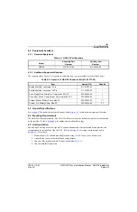
4.2 Equipment Available
4.2.1 Required Equipment
4.2.2 Additional Equipment Required
The connector kit in Table 4-2 is required to install the unit, it is not provided with the GAD 29 unit.
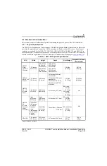
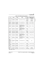
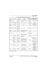
4.3 General Specifications
See
for power/current specifications, and
for dimension/weight specifications.
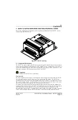
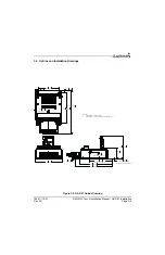
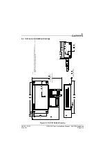
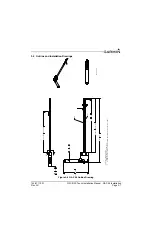
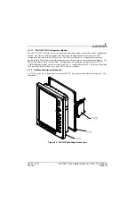
4.4 Mounting Requirements
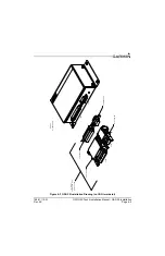
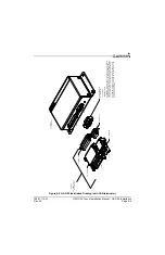
The GAD 29 will mount remotely. The GAD 29 will be secured to the airframe using four screws supplied
by the installer. Refer to
for outline and installation drawings.
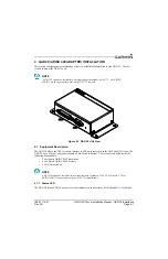
4.5 Unit Installation
Fabrication of a wiring harness is required. Sound mechanical and electrical methods and practices are
recommended for installation of the GAD 29. Refer to
for wiring considerations, and to
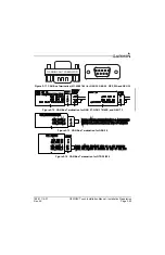
for pinouts.
1. Mount the unit to a suitable mounting location using (4) #10-32 pan or hex head screws.
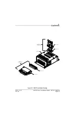
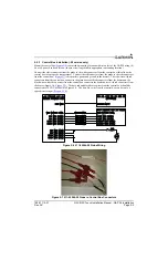
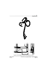
2. Assemble the connector backshells and wiring harness.
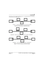
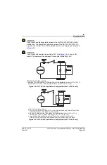
3. Connect CAN terminator to unit if required (
).
4. Connect backshell connectors.
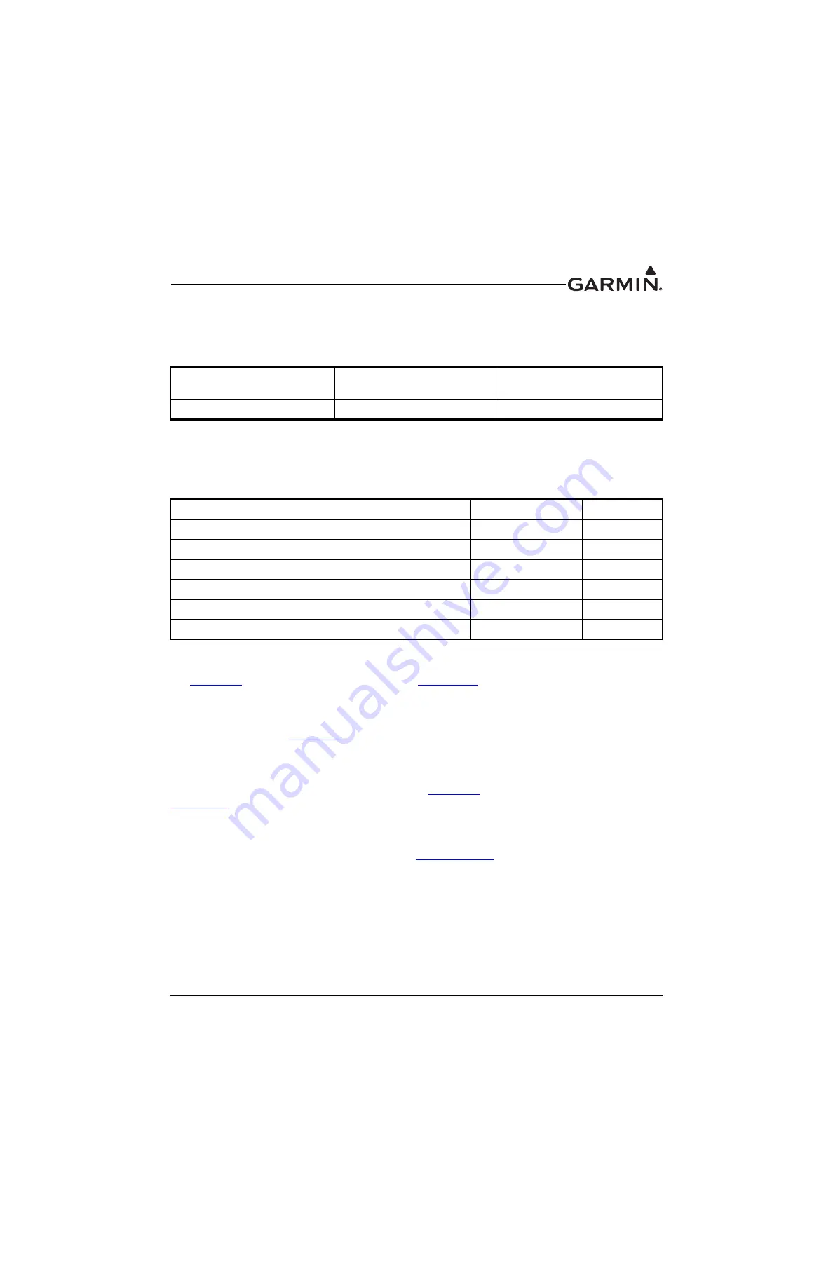
Table 4-1 GAD 29 Part Numbers
Model
Assembly Part
Number
Unit Only Part
Number
GAD 29
010-01172-00
011-03236-00
Table 4-2 Contents of GAD 29 Connector Kit (011-03271-00)
Item
Garmin P/N
Quantity
Backshell w/Hdw, Jackscrew, 9 Pin
011-01855-00
1
Backshell w/Hdw, Jackscrew, 25 Pin
011-01855-02
1
Conn, Plug,D-Sub, Crimp Pin, Commercial, 25 CKT
330-00624-25
1
Conn, Rcpt, D-Sub, Crimp Socket, Commercial, 09 CKT
330-00625-09
1
Contact, Socket, Military Crimp, Size 20
336-00022-02
11
Contact ,Pin, Military Crimp, Size 20
336-00024-00
27