190-01115-01
G3X/G3X Touch Installation Manual - LRU Pinouts
Rev. AC
Page 25-73
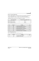
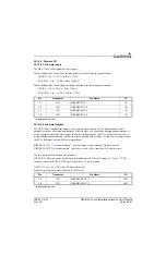
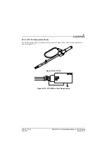
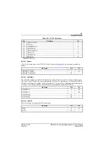
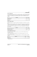
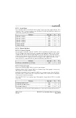
25.16.2 Power
Pins 1 & 20 supply power to the GTR 20. Refer to drawings in
for power and ground wire
gauges.
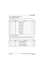
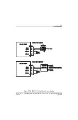
25.16.3 CAN Bus
The CAN Bus conforms to the BOSCH standard for Controller Area Network 2.0-B, and complies with
ISO 11898. Pins 25 and 26 are used to terminate the CAN bus. To terminate the CAN bus at the GTR 20,
short the pins (25 and 26) together. Refer to
for details on configuring and terminating the
CAN bus. The CAN bus on J2001 shall be used for communications between G3X LRUs.
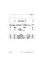
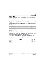
25.16.4 Unit ID
for ID connections.
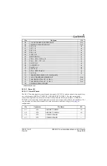
30
COPILOT HS LO
--
31
AUX 1 LO
--
32
AUX MONO IN 1
In
33
PILOT HS LO
--
34
COPILOT MIC LO
--
35
PILOT PTT*
In
36
PILOT MIC LO
--
37
MUSIC LO
In
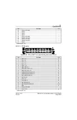
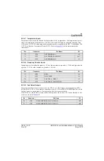
Pin Name
Pin
I/O
AIRCRAFT POWER
1
In
AIRCRAFT GROUND
20
--
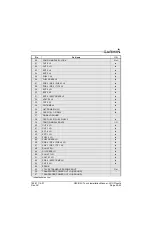
Pin Name
Pin
I/O
CAN BUS LO
6
I/O
CAN BUS HI
7
I/O
CAN TERM B
25
--
CAN TERM A
26
--
Pin Name
Pin
I/O
ID IN
8
In
ID LO
27
--
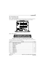
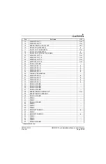
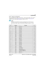
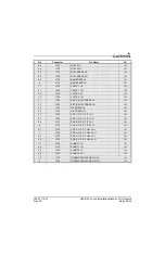
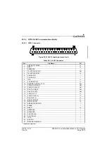
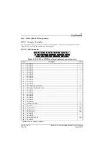
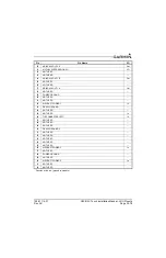
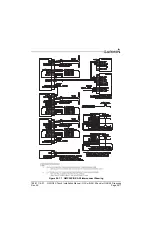
Table 25-1 J2001 Connector
Pin
Pin Name
I/O
*Indicates Active Low