

190-01115-01
G3X/G3X Touch Installation Manual - Installation Preparation
Rev. AC
Page 2-15
2.3.1 Wiring Harness Installation
Use cable meeting the applicable aviation regulation for the interconnect wiring. Any cable meeting
specifications is acceptable for the installation. When routing cables, observe the following precautions:
•
All cable routing should be kept as short and as direct as possible.
•
Check that there is ample space for the cabling and mating connectors.
•
Avoid sharp bends in cabling.
•
Avoid routing near aircraft control cables.
•
Avoid routing cables near heat sources, RF sources, EMI interference sources, power sources (e.g.,
400 Hz generators, trim motors, etc.) or near power for fluorescent lighting.
•
Route the GPS antenna cable as far as possible away from all COM transceivers and antenna
cables.
•
Analog Input wires routed too close to spark plugs, plug wires, or magnetos may result in erratic
readings.
The installer shall supply and fabricate all of the cables. Required connectors, pins, etc. are provided with
LRU Installation Kits. Electrical connections for the GMU 22 are made through a round 9-pin connector,
and are made through D subminiature connectors for all other LRUs.
defines the electrical
characteristics of all input and output signals. Required connectors and associated hardware are supplied
with the connector kit.
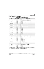
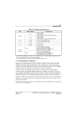
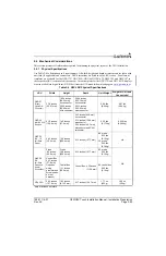
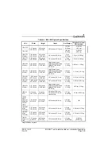
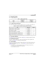
Contacts for the connectors must be crimped onto the individual wires of the aircraft wiring harness.
lists contact part numbers (for reference) and recommended crimp tools.
CAUTION
Check wiring connections for errors before connecting any wiring harnesses.
Incorrect wiring could cause internal component damage.