


G1000 Supplemental Maintenance Manual
Page 7-37
Textron Nav III Series
Revision 3
190-02128-04
Procedure B: GSU 75 or GRS 77 and GMU 44 Magnetic Calibration
NOTES
Procedure A-1 (Section 7.10.1) must first be successfully accomplished before
performing Procedure B, only for situations where the GSU/GRS was replaced
with a new unit.
On the calibr
ation pages, “GRS” refers to whichever GRS or GSU unit is
installed.
1. Start the aircraft engine following the procedures referenced in the appropriate Cessna
Nav III AFM as listed in Table 1-1.
2. After aircraft engine startup, taxi the aircraft to a properly calibrated compass rose.
3. At the compass rose, align the aircraft to a heading of magnetic north (
5°).
CAUTION
Calibration Procedure B must be carried out on a compass rose in order to
guarantee measurements free of environmental magnetic disturbances.
Attempting to carry out this maneuver on a typical ramp area may not yield a
successful calibration. The accuracy of the AHRS/ADAHRS cannot be
guaranteed if this calibration is not performed on a magnetically clean compass
rose or equivalent. If the compass rose condition is not known, it is
recommended that the technician follow the guidance in Section 7.10.2.
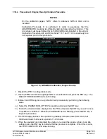
4. Restart the PFD in configuration mode.
5. Go to the GRS Page Group on the PFD.
6. Select the GRS/GMU Calibration page and enter the following softkey password:
•
9
•
10
•
11
•
12 (far right softkey)
7. Use the FMS small knob to highlight GRS/GSU for calibration and press the ENT key.
8. Using the FMS small knob, select MAGNETOMETER. Press the ENT button.
9. Use the cursor to highlight the first step in the BEFORE CALIBRATION window.
10. Follow the checklist items displayed on the PFD and press the ENT key as each one is
completed or confirmed. When the CALIBRATE field is blinking, press the ENT key to
begin the procedure.
11. The PFD display advises the operator when to turn the aircraft, when to stop, and when
to turn again.
12. Upon instruction to turn, taxi the aircraft in a right turn. After approximately 25° to 30° of
turn from the last heading, the PFD display advises the operator to stop the aircraft.
NOTE
Due to the difficulties in executing smooth, accurate turns the PFD may
incorrectly interpret a station and instruct to “HOLD POSITION” prior to full
Содержание G1000 NXi
Страница 61: ......