


Garmin G5 Electronic Flight Instrument Part 23 AML STC Installation Manual
190-01112-10
Rev. 21
Page 81
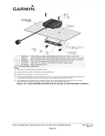
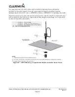
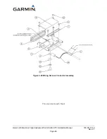
4.1.8
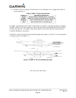
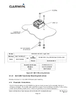
Portable Avionics Interface Connector
The portable interface connector (3P51) can be mounted to the instrument panel or a kick panel located in
the cockpit. The restrictions for mounting this connector are:
1.
Do not mount connector to yoke
2.
Maintain at least a 0.20” distance from the edge of the panel.
3.
Cannot be mounted in a plastic interior panel, composite is acceptable
4.
Connector must be electrically bonded to airframe, see section 4.5.
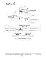
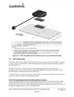
Connector can be mounted on a fabricated bracket made of 2024-T3 aluminum alloy sheet per AMS-QQ-
A-250/4 or clad 2024-T3 aluminum alloy sheet per AMS-QQ-A-250/5. Minimum sheet thickness of
0.032".
See section 5 for complete wiring interface.
4.2 Electrical Installation
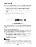
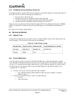
4.2.1
Special Tools
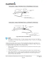
Crimp tools and positioners are required to ensure consistent, reliable crimp contact connections for the
D-sub connectors. The following crimp tools are recommended:
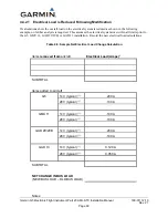
Table 4-3: Contact Crimp Tooling
Manufacturer Crimp Tool P/N
Positioner P/N
Insertion/Extraction Tool P/N
MIL-Spec
M22520/2-01
M22520/2-08
M81969/1-02
Daniels
AFM8
K13-1
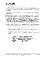
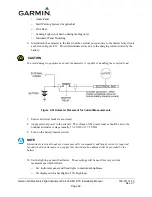
4.2.2
Power Distribution
The circuit protection device for the G5 and GAD 29/29B must be a push-pull manually resettable
circuit breaker or identically rated circuit protection device approved by the aircraft type certificate. See
Section 3.2.1 for required circuit breaker part numbers. Use the following guidance for which electrical
bus the G5 needs to be connected (Note: some aircraft manufacturers may label the battery bus as
“essential bus” or “main bus”):
•
G5 needs to be connected to the battery bus when installed:
o
As an Attitude Indicator (ADI), installed in either the turn coordinator or attitude
indicator position
•
G5 needs to be connected to the avionics bus when installed:
o
As a HSI
o
In the DG position


