Garmin G5 Electronic Flight Instrument Part 23 AML STC Installation Manual
190-01112-10
Rev. 21
Page 43
4
INSTALLATION PROCEDURES
4.1 Mechanical Installation
4.1.1
Special Tools Required
Laser Square
For GMU 11 magnetometer installations it is recommended (but optional) to use a laser square with a line
accuracy of ± 3/32 inches end-to-end, at 15 feet perpendicular distance (or better). A Stanley Laser Level
Square 77-188 S2 meets the line accuracy requirement.
Digital Level
It is recommended to use a digital level when installing GMU 11 magnetometer.
Protractor Tool
A protractor tool may be required to measure the angle offset during the magnetometer installation.
Plumb Bob
A plumb bob may be required for leveling and installing the magnetometer unit.
Aircraft Jack Set
A set of aircraft jacks may be required for stabilizing the aircraft after it is leveled.
4.1.2
G5 Mounting Requirements
NOTE
It is important that the G5 is installed perpendicular to the aircraft's longitudinal axis (display
bezel parallel to the wing spar carry thru) and as close to level in the roll axis as possible. Small
roll offsets and pitch offsets, up to 15°, can be corrected for during calibration.
In addition to the installation limitations in Section 2.1, consider the following when selecting a mounting
location for the G5:
•
Protect the mounting location for the G5 from rapid thermal transients, in particular large heat
loads from nearby high-power equipment.
•
Do not install the G5 within 1 inch of magnetically mounted antennas, speaker magnets, or other
strongly magnetic items.
•
If installing dual G5s above and below each other, a minimum spacing of 3.6 inches center to
center is required, see Section 4.1.2.4 for more information.
•
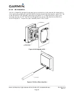
Two Adapter Plates must be used if installing the G5 in an instrument hole with any cutout for
instruments knobs. See Figure 4-10 and Figure 4-12 for more information.
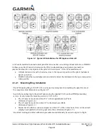
One or two G5s may be installed. See Figure 4-1 for typical installation configurations in an IFR
approved aircraft.

