background image

AFTER SALES SUPPORT

AFTER SALES SUPPORT

01904 727 506

01904 727 506

0124 75150

0124 75150

www.coreservice.co.uk

www.coreservice.co.uk

27

28

3.6V Cordless mini grass & hedge trimmer

3.6V Cordless mini grass & hedge trimmer

GB

GB

IRE

IRE

GB

IRE

GB

IRE

Operation

Operation

Take off the Blades

WARNING! DO NOT operate the switch before 
dismantling or fitting the blades. Risk of injury!

The blade can be changed rapidly and expediently 
without any tools.

Follow the steps as shown in the upper figure. (See Fig. E) 

To change the blade, you must remove the Blade cover (A) at first. 

1.   Hold the machine in one hand as shown in the figure E, with 

the handle towards your body. Lever the retainer (B) upwards 
with your thumb whilst sliding the cover backwards. 

2.   Hold the blade cover firmly and pull it backwards.

3.   Remove the blade cover upwards.

4.  Take off the blades and install another blade. 

After you take off the blades you will see the gear wheels(See Fig. F).

Make sure that no dirt

grass and leaves get in the gear.

Important! If there are grasses or leaves around the gear 
please clean them.

Installing the hedge/shrub blades

1.   Turn the gear wheel so that the middle line of the marking 

rib on the gear wheel is exactly positioned downwards or 
upwards. (See Fig F)

2.   Move the upper blade of the hedge/shrub blades so that the 

middle line of the plastic ring is positioned exactly align the 
centre of the hole.(See Fig G).

3.   Guide the four locking holes of the hedge/shrub blades with 

the four locking pins on the gear carriage. Make sure that the 
cam of the gear wheel snaps into the plastic ring entirely. 

4.  Install the blade cover. 

Installing the grass trimmer blades

1.   Turn the gear wheel so that the middle line of the marking rib 

on the gear wheel is positioned exactly leftwards. (See Fig H).

2.   Move the upper blade of the grass blades so that the middle 

line of the plastic ring is positioned exactly aligned with the 
centre of the hole.(See Fig I).

3.   Guide the four locking holes of the grass blades with the four 

locking pins on the gear carriage. Make sure that the cam of 
the gear wheel snaps into the plastic ring entirely.

Содержание GL3.6GS

Страница 1: ...ety directions for hedge trimmers 19 Furthersafetydirections 20 Special safety directions for battery operated tools 21 Safety directions for the battery charger 22 Checking the box contents 24 Operat...

Страница 2: ...GB IRE IRE GB Product images and parts list Product images and parts list 3 4 A B D C 6 1 2 5 4 11 1 2 3 10 6 8 8 9 9 7 7 5 12...

Страница 3: ...uct images and parts list Product images and parts list 5 6 E G H F A B Gear Wheel Middle Line Gear Wheel Gear Wheel Middle Line Gear Wheel Nether Blade Hole Upper Blade Middle Line Plastic ring Middl...

Страница 4: ...Cover 5 Battery Pack 6 Charger 7 Charger Plug 8 Charger Hole 9 Charge Indicator 10 Hedge Trimmer Blade 11 Retainer 11 Blade cover J Products images and parts list General information I 1 2 3 4 5 6 7 8...

Страница 5: ...dless mini grass hedge trimmer on to third parties please be absolutely sure to include this instruction manual You can request an electronic version of these instructions from our customer service Ex...

Страница 6: ...pletelystopped Caution Be careful of falling objects Keep hands away from blades symbols on the battery pack Do not expose the battery pack to sunlight or increased temperatures Do not dispose of a ba...

Страница 7: ...ose control 2 Electrical safety a Power tool plugs must match the outlet Never modify the plug in any way Do not use any adapter plugs with earthed grounded power tools Unmodified plugs and matching o...

Страница 8: ...ur hair clothing and gloves away from moving parts Loose clothes jewellery or long hair can be caught in moving parts g If devices are provided for the connection of dust extraction and collection fac...

Страница 9: ...s coins keys nails screws or other small metal objects that can make a connection from one terminal to another Shorting the battery terminals together may cause burns or a fire d Under abusive conditi...

Страница 10: ...een the cutting blade and a live cable may render metallic components live and result in an electric shock d Before the work search the hedge for concealed objects e g cable etc To avoid damaging the...

Страница 11: ...battery to strong sunlight or hot environment over long periods of time Heat damages the battery and there is a risk of explosion b Allow a hot battery to cool before charging c Do not open up the ba...

Страница 12: ...d it must be replaced by the manufacturer a customer service agent of the same or a similarly qualified person in order to prevent hazards l Do not use the charger to charge non rechargeable batteries...

Страница 13: ...idge See Fig C Attention The moving blade will move back if the moving blade is not in the fully open position when inserting the battery pack Charging Battery Warning Do not use other battery charger...

Страница 14: ...no dirt grass and leaves get in the gear Important If there are grasses or leaves around the gear please clean them Installing the hedge shrub blades 1 Turn the gear wheel so that the middle line of t...

Страница 15: ...h off the device immediately 1 Guide the device along the edge of the lawn Cutting hedges NOTICE Risk of damage to the unit Be especially careful when working near fences If cut material such as fence...

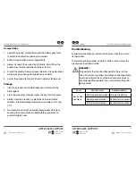
Страница 16: ...ill directly affect the cut ting performance Never clean the product with a water jet or high pressure cleaner The motor must remain dry Do not use aggressi ve cleaning agents such as cold cleaner or...

Страница 17: ...ery pack defective Contact service center Is the device defective Contact service center Storage Troubleshooting Transportation 1 Switch the product off and disconnect the battery pack from the machin...

Страница 18: ...ion point in the community borough This ensures that old devices are recycled in a professional manner and also rules out negative consequences for the environment Technical Data Unit Model GL3 6GS Ba...

Страница 19: ...g idle in addition to the trigger time The sound intensity level for the operator may exceed 85dB A and ear protection measures are necessary Declaration of CE Conformity We SUMEC Hardware Tools Co Lt...

Страница 20: ...om date of purchase Costs Free repair exchange or refund No transport costs Hotline Support line charged at local rate ADVICE Please contact our service hotline by phone e mail or fax before sending i...

Страница 21: ...rse of the first 3 years after date of purchase we will remedy the problem as quickly as possible once it has been brought to our attention In the unlikely event of such an occurrence or if you requir...

Отзывы: