background image

3.10.4.2 To set the SensorControl frequency
Set how frequently the product cuts the grass

when the 

SensorControl is in use. There are 3

frequency levels: 

Low, Mid and High. The higher

the frequency, the more sensitive the product is

to the grass growth. That is, if the grass growth is

high then the product is allowed to work longer.

Note: If the mowing results are not optimal when

using 

SensorControl, the schedule settings may

need adjusting. Do not restrict the schedule more

than necessary. Also, check that the blade disc is

clean and that the blades are in good condition.

1. Do steps 1–3 in 

To get access to the menu

on page 23.

2. Use the arrow buttons and the OK button to

move through the menu structure

SensorControl > Cutting time.

3. Use the arrow buttons to select 

Low, Mid or

High frequency.

4. Push the BACK button.

3.10.5 Security level

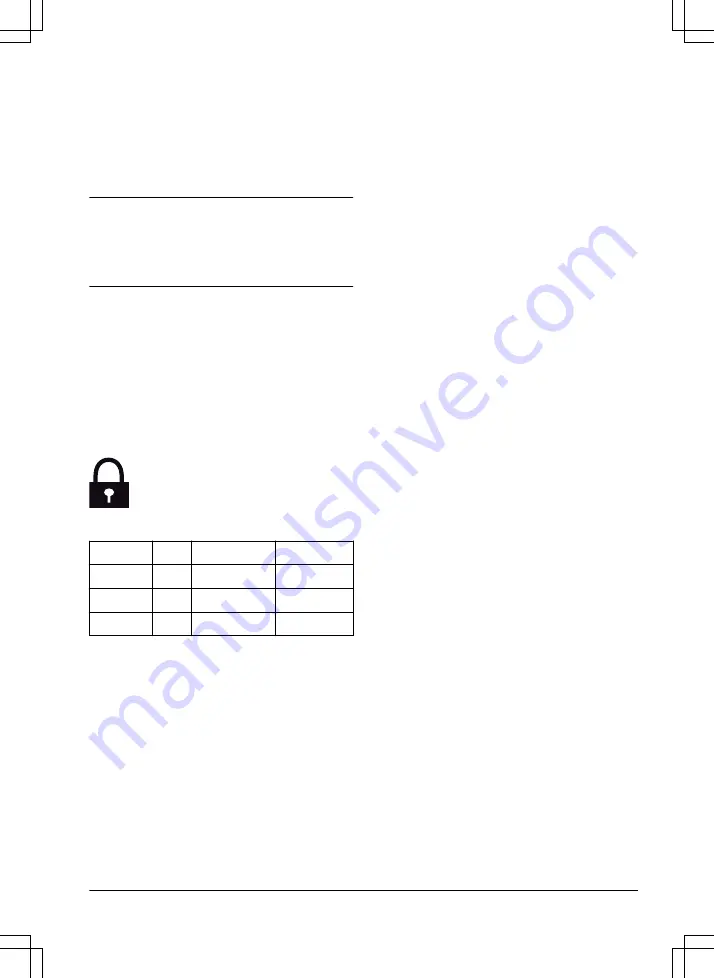
There are 3 security levels for .

Function

Low

Medium

High

Alarm

X

PIN-code

X

X

Time lock

X

X

X

Alarm - An alarm goes off if the PIN-code is

not entered within 10 seconds after the

STOP button is pushed. The alarm also

goes off when the product is lifted. The

alarm stops when the PIN-code is entered.

PIN-code - The correct PIN-code must be

entered to get access to the Menu structure

of the product. If the incorrect PIN-code is

entered 5 times, the product is locked for a

time. The lock is extended for each new

incorrect try.

Time lock - The product locks if the PIN-

code has not been entered in 30 days. Enter

the PIN-code to get access to the product.

3.10.5.1 To set the security level
Select 1 of the security levels for your product.
1. Do steps 1–3 in 

To get access to the menu

on page 23.

2. Use the arrow buttons and the OK button to

move through the menu structure 

Settings >

Security > Security level.

3. Use the arrow buttons and the OK button to

select the level of security.

4. Push the OK button.

3.10.6 Security - Advanced

3.10.6.1 To create a new loop signal
The loop signal is randomly selected to create a

unique link between the product and the charging

station. In rare cases, there may be a need to

generate a new signal, for instance if two

adjacent installations have very similar signals.
1. Put the product in the charging station.
2. Do steps 1–3 in 

To get access to the menu

on page 23.

3. Use the arrow buttons and the OK button to

move through the menu structure 

Settings >

Security > Advanced > New loop signal.

4. Wait for confirmation that the loop signal has

been generated. This usually takes about 10

seconds.

3.10.6.2 To change the PIN-code
1. Do steps 1–3 in 

To get access to the menu

on page 23.

2. Use the arrow buttons and the OK button to

move through the menu structure 

Settings >

Security > Advanced > Change PIN-code.

3. Enter the new PIN code.
4. Push the OK button.
5. Enter the new PIN code again.
6. Push the OK button.
7. Make a note of the new PIN code. Refer to 

Introduction on page 3.

3.10.7 Lawn Coverage

If the work area includes remote parts that are

connected with narrow passages, the 

Lawn

Coverage function is useful to be able to maintain

a well-cut lawn in all parts of the yard. A guide

wire must be installed to use the functions. You

can set a maximum of 3 remote areas.

1378 - 003 - 16.04.2020

Installation - 25

Содержание SILENO+

Страница 1: ...gardena com Operator s manual SILENO smart SILENO InDesign_P15G_omslag_A5 indd 1 InDesign_P15G_omslag_A5 indd 1 ...

Страница 2: ... installation of the product 22 3 10 To do the product settings 23 4 Operation 4 1 Main switch 31 4 2 To start the product 31 4 3 Operating mode Start 31 4 4 Operating mode Park 32 4 5 To stop the product 32 4 6 To switch off the product 32 4 7 Schedule and Standby 32 4 8 To charge the battery 33 4 9 Adjust the cutting height 33 5 Maintenance 5 1 Introduction maintenance 34 5 2 Clean the product 3...

Страница 3: ...y wire The front of the product always passes the boundary wire by a specific distance before the product turns around When the product hits an obstacle or approaches the boundary wire the product selects a new direction The operator selects the operation settings with the keys on the keypad The display shows the selected and possible operation settings and the operation mode of the product 1 1 2 ...

Страница 4: ...tes 9 LED for operation check of the charging station and boundary wire 10 Charging station 11 Rating plate 12 Display 13 Keypad 14 Cutting system 15 Chassis box with electronics battery and motors 16 Handle 17 Main switch 18 Battery cover 19 Blade disc 20 Power supply1 21 Loop wire for boundary loop and guide wire 22 Couplers for loop wire 23 Stakes 24 Connector for the loop wire 25 Screws for se...

Страница 5: ... applicable EC Directives Noise emission to surroundings The product s emissions are set out in Technical data on page 49 and on the rating plate It is not permitted to dispose this product as normal household waste Ensure that the product is recycled in accordance with local legal requirements The chassis contains components which are sensitive to electrostatic discharge ESD The chassis must also...

Страница 6: ...roduct charges the symbol flashes The product is in the charging station but do not charge the battery The product is set in ECO mode 1 5 Symbols on the battery Read the user instructions Do not discard the battery into fire and do not expose the battery to a heat source Do not immerse the battery into water 1 6 General manual instructions The following system is used in the Operator s Manual to m...

Страница 7: ...week Sa Fr Th We Tu Mo All days Reset smart SILENO On Off Low Medium High Cutting time SensorControl smart system Good Poor Bad Connected Yes No Signal strength Status Exclude device Security Low Medium High Change PIN code New loop signal Security level Advanced 1378 003 16 04 2020 Introduction 7 ...

Страница 8: ... often How far Disable Reset Test More Exit angles Corridor width Reversing distance Drive past wire Advanced Settings ECO mode Time date Set time Set date Time format Date format Language Country Reset all user setting About General On Off 8 Introduction 1378 003 16 04 2020 ...

Страница 9: ... the START button A to start the operation of the product Use the BACK button B to move up in the menu lists Use the arrow buttons C to navigate in the menu Use the OK button D to confirm the settings you select in the menus Use the MENU button E to go to the main menu Use the PARK button F to send the product to the charging station Use the number buttons G to enter PIN code time and date A E F B...

Страница 10: ...ledge if they have been given supervision or instruction concerning use of the appliance in a safe way and understand the hazards involved Local regulations may restrict the age of the operator Cleaning and maintenance shall not be made by children without supervision Never connect the power supply to an outlet if the plug or cord is damaged Worn or damaged cord increase the risk of electric shock...

Страница 11: ... necessary in a given situation 2 3 Safety instructions for operation 2 3 1 Use The product may only be used with the equipment recommended by the manufacturer All other types of use are incorrect The manufacturer s instructions with regard to operation maintenance must be followed precisely Warning signs shall be placed around the work area of the product if it is used in public areas The signs s...

Страница 12: ...ct on page 32 Do not put anything on top of the product or its charging station Do not allow the product to be used with a defective guard blade disc or body Neither should it be used with defective blades screws nuts or cables Never connect a damaged cable or touch a damaged cable before it is disconnected from the supply Do not use the product if the Main switch does not work Always switch off t...

Страница 13: ...ng or maintenance of the charging station or the loop wire CAUTION Never use a high pressure washer or even running water to clean the product Never use solvents for cleaning Inspect the product weekly and replace any damaged or worn parts Refer to Maintenance on page 34 2 3 5 In the event of a thunderstorm To reduce the risk of damage to electrical components in the product and the charging stati...

Страница 14: ...on carefully Make a blueprint of the work area and include all obstacles This makes it easier to see the ideal positions for the charging station the boundary wire and the guide wire Make a mark on the blueprint where to put the charging station the boundary wire and the guide wire Make a mark on the blueprint where the guide wire connects to the boundary wire Refer to To install the guide wire on...

Страница 15: ... good airflow Use a residual current device RCD when you connect the power supply to the power outlet Low voltage cables of different lengths are available as accessories 3 4 3 To examine where to put the boundary wire CAUTION There must be an obstacle of minimum 15 cm 6 in in height between the boundary wire and water bodies slopes precipices or public roads This will prevent damage to the produc...

Страница 16: ...5 cm 0 4 2 in high 1 5 cm 0 4 2 30 cm 12 Put the boundary wire 10 cm 4 in D from an obstacle that is less than 1 cm 0 4 in high 10 cm 4 max 1 cm 0 4 If you have a paving stone path that is in level with the lawn put the boundary wire below the paving stone Note If the paving stone is minimum 30 cm 12 in wide use the factory setting for the Drive Past Wire function to cut all the grass adjacent to ...

Страница 17: ...onnects 2 parts of the work area The distance between the boundary wire on each side in the passage must be a minimum of 60 cm 24 in Note If a passage is less than 2 m 6 5 ft wide install a guide wire through the passage The minimum distance between the guide wire and the boundary wire is 30 cm 12 in The product always runs to the left of the guide wire as seen facing the charging station It is re...

Страница 18: ...s the main area A Note The product must be manually moved between the main area and the secondary area B A Put the boundary wire around the secondary area B to make an island Refer to To make an island on page 17 Note The boundary wire must be put as 1 loop around all of the work area A B Note When the product cuts grass in the secondary area the Secondary area mode must be selected Refer to Opera...

Страница 19: ...in distance C The settings can be changed in Lawn Coverage on page 25 If the work area includes a secondary area D refer to To make a secondary area on page 18 Put the product in the secondary area and select Secondary area mode B D A C 3 5 Installation of the product 3 5 1 Installation tools Hammer plastic mallet To simplify putting the stakes into the ground Edge cutter straight spade To bury th...

Страница 20: ...the screws to the ground until the guide wire is installed Refer to To install the guide wire on page 21 3 Connect the low voltage cable to the charging station 4 Put the power supply at a minimum height of 30 cm 12 in min 30 cm 12 5 Connect the power supply cable to a 100 240V power outlet Note When the charging station is connected it is possible to charge the product Place the product in the ch...

Страница 21: ... guide wire through the slot in the charging station plate 5 Push the connector onto the metal pin on the charging station with the mark Guide 6 Disconnect the charging station from the power outlet 7 Put the end of the guide wire at the eyelet on the boundary wire 8 Cut the boundary wire with a pair of wire cutters 9 Connect the guide wire to the boundary wire with a coupler a Put the 2 ends of t...

Страница 22: ...wer outlet 2 Cut the boundary wire or the guide wire with a pair of wire cutters where it is necessary to install the extension 3 Add wire where it is necessary to install the extension 4 Put the boundary wire or the guide wire into position 5 Put the wire ends into a coupler Note Make sure that you can see the ends of the boundary wire or the guide wire through the transparent area of the coupler...

Страница 23: ...rol smart system only for smart SILENO Settings Installation Security Refer to Menu structure overview 1 on page 7 and Menu structure overview 2 on page 8 3 10 2 To get access to the menu 1 Push the STOP button 2 Use the number buttons and the OK button to enter the PIN code 3 Push the MENU button 3 10 3 Schedule Note The lawn should not be cut too often to obtain the best result If the product is...

Страница 24: ...e menu on page 23 2 Use the arrow buttons and the OK button to move through the menu structure Schedule Overview Reset a Push the arrow buttons to select Current day to only reset the current day to factory settings b Push the arrow buttons to select All week to reset all schedule settings to factory settings 3 Push the OK button 3 10 4 SensorControl SensorControl automatically adjust the cutting ...

Страница 25: ... the product 3 10 5 1 To set the security level Select 1 of the security levels for your product 1 Do steps 1 3 in To get access to the menu on page 23 2 Use the arrow buttons and the OK button to move through the menu structure Settings Security Security level 3 Use the arrow buttons and the OK button to select the level of security 4 Push the OK button 3 10 6 Security Advanced 3 10 6 1 To create...

Страница 26: ... the exit angles on page 27 9 Push the BACK button 3 10 7 2 To do a test of the Lawn Coverage function 1 Put the product in the charging station 2 Do step 1 3 in To get access to the menu on page 23 3 Use the arrow buttons and the OK button to move through the menu structure Installation Lawn Coverage Area 1 3 More Test 4 Push the OK button 5 Push the START button 6 Close the hatch 7 Make sure the...

Страница 27: ... cm 24 ft 3 10 9 1 To set the reversing distance 1 Do steps 1 3 in To get access to the menu on page 23 2 Use the arrow button and the OK button to move through the menu structure Installation Advanced Reversing distance 3 Use the number buttons to set the distance 4 Push the BACK button 3 10 10 Drive Past Wire The front of the product always moves past the boundary wire by a specified distance be...

Страница 28: ...tons and the OK button to move through the menu structure Settings General Time Date 3 Use the number buttons to set the time and then push the BACK button 4 Use the number buttons to set the date and then push the BACK button 5 Use the arrow buttons to set the time format and then push the BACK button 6 Use the arrow buttons to set the date format and then push the BACK button 3 10 13 2 To set th...

Страница 29: ...e the number buttons to enter the PIN code and push the OK button 5 The inclusion code is shown in the product display 6 Follow the instructions in the GARDENA smart system app The inclusion sequence might take several minutes Once the inclusion has succeeded you will automatically return to the product start screen If the inclusion by any reason fails try again 3 10 14 2 Inclusion in the App The ...

Страница 30: ...ucture smart system Status Note The Status is either connected Yes or not connected No The Signal strength is either Good Poor or Bad Put the charging station in a location with Signal strength Good for the best smart system performance 30 Installation 1378 003 16 04 2020 ...

Страница 31: ...ly leaves the charging station when the battery is fully charged and if the schedule allows the product to operate Note The first weeks after installation the perceived sound level when cutting the grass may be higher than expected When the product has cut the grass for some time the perceived sound level is much lower 4 3 Operating mode Start Push the START button to select the following operatin...

Страница 32: ...harging station where it stays until a new operation mode is selected and the START button is pushed 4 4 2 Start again with next schedule The product stays in the charging station until the next Schedule setting permits operation This operating mode is suitable if you want to cancel an ongoing mowing cycle and allow the product to stay in the charging station until the next day 4 5 To stop the pro...

Страница 33: ...e product is new or has been stored for a long period the battery can be empty and needs to be charged before starting In the Main area mode the product automatically alternates between mowing and charging 1 Set the Main switch to position 1 2 Place the product in the charging station Slide the product in as far as possible to ensure proper contact between the product and the charging station Refe...

Страница 34: ...y and more energy is needed resulting in the product not mowing such a large area 5 2 Clean the product CAUTION Never use a high pressure washer or running water to clean the product Never use solvents for cleaning The product does not operate satisfactorily in slopes if the wheels are blocked with grass Use a soft brush to clean the product GARDENA offers a special cleaning and maintenance kit as...

Страница 35: ...e hatch 4 Remove the 3 screws with a screwdriver 5 Remove the 3 blades 6 Attach 3 new blades and screws 7 Make sure that the blades can pivot freely 5 4 Firmware update If service is done by GARDENA customer service then available firmware updates are downloaded to the product by the service technician Owners of GARDENA products can update the firmware if this is initiated by GARDENA Registered us...

Страница 36: ...1 To replace the battery WARNING The product must be disconnected from the supply mains when removing the battery 1 Set the Main switch to position 0 2 Turn the product upside down Place the product on a soft and clean surface to avoid scratching the body and the display cover 3 Clean around the battery cover 4 Unscrew the screws to the battery cover Torx 20 and remove the battery cover 5 Release ...

Страница 37: ...e product Make sure that the grass is maximum 10 cm 3 9 in Trapped The product is stuck in a small area be hind a number of obstacles Check if there are any obstacles which make it hard for the product to move on from this location Remove the obsta cles or put the boundary wire around the obstacle to create an island Refer to To make an island on page 17 Outside working area The boundary wire conn...

Страница 38: ...wet grass wait until the lawn has dried be fore using the product The work area includes a steep slope Steep slopes should be isolated Refer to To examine where to put the boun dary wire on page 15 The guide wire is not laid diagonally in the slope Make sure that the guide wire is instal led diagonally across the slope Refer to To examine where to put the guide wire on page 18 Wheel motor over loa...

Страница 39: ...roduct is set to the Secondary area operating mode Put the product in the charging station Next start hh mm The schedule setting prevents the product from operating Change the schedule settings Refer to Schedule on page 23 The rest period is in progress The product has an inbuilt standby period according to the Standby time table This behavior is normal and no action is required The clock or date ...

Страница 40: ...s The temperature in the battery is too high or too low to start operation No action The product will start to op erate when the temperature is in limits Charging current too high Wrong or faulty power supply unit Restart the product If the problem stays speak to your authorized service technician Connectivity prob lem Potential problem on the connectivity circuit board in the product Restart the ...

Страница 41: ...e product in the charging station start the product and close the hatch The boundary wire is crossed on its way to and from an island Check that the boundary wire is laid ac cording to instructions e g in the right direction around the island Refer to To install the boundary wire on page 20 The pairing between the product and the charging station is lost Put the product in the charging station and...

Страница 42: ...ntact plates using a fine grade emery cloth If the problem stays speak to your approved servicing dealer Settings restored Confirmation that Reset all user set tings has been carried out No action Guide not found The guide wire is not connected to the charging station Check that the guide wire connector is tightly connected to the charging sta tion Refer to To install the guide wire on page 21 Bre...

Страница 43: ...er to ECO mode on page 28 Blue flashing light The boundary loop is not connected to the charging station Check that the boundary wire connec tors are fitted properly to the charging station Refer to To install the boundary wire on page 20 Break in the boundary loop Find out where the break is Replace the damaged section of the loop with a new loop wire and splice using an origi nal coupler Red fla...

Страница 44: ... Set the clock or date Refer to To set the time date on page 28 The start and stop times for mowing are incorrect Change the Schedule settings Refer to To set the schedule on page 23 The product vi brates Damaged blades lead to imbalance in the cutting system Inspect the blades and screws and re place them if necessary Refer to Re place the blades on page 35 Too many blades in the same position le...

Страница 45: ...o a remote area Re fer to Lawn Coverage on page 25 The How often setting is incorrect in relation to the layout of the work area Check that the correct How often val ue is selected The work area is too large Try limiting the work area or extending the schedule Refer to Schedule on page 23 Dull blades Replace all the blades Refer to Re place the blades on page 35 Long grass in relation to the set c...

Страница 46: ...fer to Indicator lamp in the charging station on page 43 2 Check that the boundary wire connections to the charging station are properly connected and not damaged Check that the indicator lamp in the charging station is still flashing blue POWER AR AL G1 3 Switch the connections between the guide wire and the boundary wire in the charging station Start by switching connection AL and GUIDE If the i...

Страница 47: ...the difference between a solid green light and a flashing blue light Then follow instruction in step 5 below 4 If indicator lamp still flashes blue in step 3 above Put AL and GUIDE back in their original positions Then switch AR and GUIDE If indicator lamp now is lit with a solid green light then disconnect AL and connect a new boundary wire to AL Connect the other end of this new wire at the midd...

Страница 48: ...duct in a dry frost free space Keep the product with all wheels on level ground during storage or use a wall hanger If you keep the charging station indoors disconnect and remove the power supply and all the connectors from the charging station Put the end of each connector wire in a connector protection box Note If you keep the charging station outdoors do not disconnect the power supply and the ...

Страница 49: ...h Art No 584 85 28 04 Power supply 28V DC V AC 100 240 Low voltage cable length m ft 10 33 Mean energy consumption at maximum use 10 kWh month in a 2000 m2 work area Charge current A DC 1 3 Type of Power Supply Unit FW7312 ADP 40BR Average mowing time min 65 Average charging time min 60 Boundary wire antenna SILENO R160Li R160LiC R200Li R200LiC Operating Frequency Band Hz 300 80000 Maximum Radio f...

Страница 50: ...assification SILENO R160Li R160LiC R200Li R200LiC Product IPX4 Charging station IPX1 Power supply IPX4 Internal SRD short range device R160Li R200Li R160LiC R200LiC Operating frequency band MHz 863 870 Maximum transmitted power dBm 25 Free field radio range approx m 100 7 Noise emissions in the environment measured as sound power LWA in conformity with EC di rective 2000 14 EC and New South Wales ...

Страница 51: ...of wireless systems such as remote controls radio transmitters hearing loops underground electric animal fencing or similar The products are made in England or the Czech Republic See information on the rating plate Refer to Product overview on page 4 1378 003 16 04 2020 Technical data 51 ...

Страница 52: ...nty Damage caused by water seepage from using a high pressure washer or from being submerged under water for example when heavy rain forms pools of water Damage caused by lightning Damage caused by improper battery storage or battery handling Damage caused by using a battery that is not a GARDENA original battery Damage caused by not using GARDENA original spare parts and accessories such as blade...

Страница 53: ...r to Technical data on page 49 for information regarding noise emissions and the cutting width The notified body 0404 RISE SMP Svensk Maskinprovning AB Box 7035 SE 750 07 Uppsala Sweden has issued a report regarding the assessment of conformity according to annex VI to the Council s Directive of May 8 2000 relating to noise emissions into the environment 2000 14 EC The certificate is numbered 01 9...

Страница 54: ...54 EC Declaration of Conformity 1378 003 16 04 2020 ...

Страница 55: ...1378 003 16 04 2020 EC Declaration of Conformity 55 ...

Страница 56: ...IGINAL INSTRUCTIONS We reserve the right to make changes without prior notice Copyright 2020 GARDENA Manufacturing GmbH All rights reserved 114 18 55 26 InDesign_P15G_omslag_A5 indd 2 InDesign_P15G_omslag_A5 indd 2 ...

Отзывы: