TR-RT LED lighting controllers - User Manual
5
Mounting the TR-RT
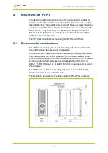
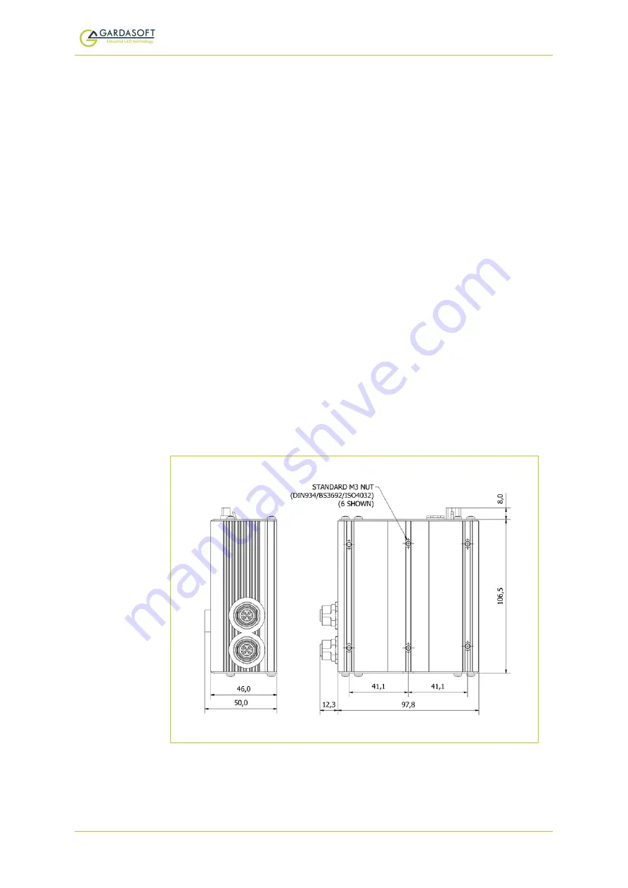
In order to provide fixing points to mount the unit onto a flat surface or
bracket, insert M3 nuts into one or more of the slots in the base, see the
illustration below. The quantity and position of these nuts depends on the
user’s requirements. One of the end covers features cut-outs to allow the
M3 nuts to be easily slid into place without dismantling the controller.
Ensure that the fixing screws used do not extend past the lower base
surface by more than 5.5mm.
The PP704 kit is available for mounting the TR-RT on a DIN rail.
5.1
Environmental considerations
The TR-RT enclosure is a fire enclosure as long as it is mounted so that
none of the connectors are facing downwards.
If a fire enclosure is used, the enclosure should be metal or plastic (with a
flammability rating of UL94 V1 or better); with no holes below or to the
sides of the TR-RT when mounted. Cable entries below the TR-RT should
be through glands that also have a flammability rating of UL94 V1 or
better. The TR-RT should be at least 10mm from any other part or side of
the enclosure.
The TR-RT does not have an IP rating and must be mounted so that
moisture and dirt cannot enter the unit.
The illustration below shows the dimensions of a TR-RT2xx controller:
—
13
—


