


Installation
5
· G&D DP1.2-MUX3-ATC
Installation
We recommend connecting the cables in blocks and from bottom to top. This pre-
vents cables that are already plugged in from blocking the view of the interface
names.
Overview of the interfaces
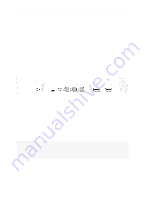
Front panel of the KVM switch
The front panel of the KVM switch provides two USB 3.0 interfaces to connect any
USB devices. If a printer or mass storage device is connected to one of these inter-
faces, these devices are available to the active computer.
The front panel also provides a service port, which is usually
not
used during opera-
tion.
In addition to the interfaces, the front panel provides three buttons for selecting the
active channel and several LEDs (see
Back panel of the KVM switch
The interfaces for connecting the workstation devices and the computers are located
on the back panel of the KVM switch. You can find a detailed description of the
interfaces on the following pages.
Setting up the device
1. Make sure that the computers you want to connect to the KVM switch are turned
off. If the computers are equipped with keyboard and mouse devices, disconnect
the cables of these devices from the PS/2 or USB interfaces.
2. Place the KVM switch between the computers and the workstation. Note the
maximum cable length of two meters between the KVM switch and the comput-
ers to be connected.
Figure 1: Section of the front panel of the KVM switch
IMPORTANT:
Due to the use of heatpipes, the device must be installed in such a
way that the front panel is
not
located below the rear panel.
In addition, do
not
install the device with the unslotted side profile above the slot-
ted side profile.
Service
CPU 1
CPU 2
CPU 3
USB 3.0 Devices
Status
Ready
System
Fail
Ident.
Main
Red.
Power
Содержание DP1.2-MUX3-ATC
Страница 93: ... Deutsch ...
Страница 185: ... English ...
Страница 186: ... ...
Страница 187: ... English ...


