background image

G

AMATRONIC 

E

LECTRONIC 

I

NDUSTRIES 

L

TD

.


CENTRIC 3x480, User Guide, rel. 1.7 

77 


7.3


OPERATION 


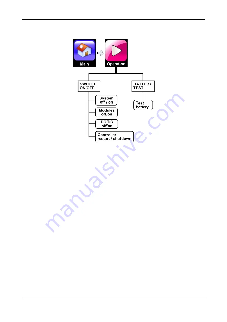
Figure 58:  The "Operation" option on the main menu 


7.3.1 

Operation > SWITCH ON/OFF 

This function is used to turn the UPS on and off. Pressing the "ON/OFF" button on the main screen also 
brings you to this option. 

7.3.1.1


OPERATION > SWITCH ON/OFF > SYSTEM OFF 

Turning the system OFF disconnects the load. 

7.3.1.2


OPERATION > SWITCH ON/OFF > SYSTEM ON 

Turns the modules ON and moves the load from bypass mode to inverter mode. 
This function reverses a "Modules OFF" command. 

7.3.1.3


OPERATION > SWITCH ON/OFF > MODULES OFF 

Turns the power modules OFF. If all modules are shut off the load is automatically moved to bypass. 

7.3.1.4


OPERATION > SWITCH ON/OFF > MODULES ON 

Switches the power modules ON. After a short wait the load is automatically transferred to the inverter. 

7.3.1.5


OPERATION > SWITCH ON/OFF > DC/DC OFF 

Switches off a dc/dc module. Each dc/dc modules services two UPS modules 
If a dc-dc block is switched off, its two associated UPS module will still function normally, except that in 
battery mode there will not be any dc current supplied to those modules. (There is no common dc bus 
between the UPS modules.) 


Содержание Centric 3x480 Vac

Страница 1: ...mail info gamatronic co il Website www gamatronic com 2MUM PPCN 5 U UP PS S S SY YS ST TE EM M 3 3X X4 48 80 0 V VA AC C U US SE ER R G GU UI ID DE E f fo or r t th he e 1 12 20 0 k kW W a an nd d 2 2...

Страница 2: ...ible for any damage or malfunction due to incorrect wiring of the batteries Gamatronic is not liable for and the Purchaser waives any right of action it has or may have against Gamatronic for any cons...

Страница 3: ...R INTERFACE 11 4 1 Control panel 11 4 1 1 Calibrating the touch screen 11 4 2 Buttons and LEDs on the system controller 12 4 2 1 UPS off button 12 4 2 2 Alarm LED 12 4 2 3 CPU active LED 13 4 2 4 CPU...

Страница 4: ...Battery BATTERY CURRENT 41 7 2 4 3 End of Backup voltage limit 42 7 2 4 4 Battery floating voltage 42 7 2 4 5 Batteries per cabinet 42 7 2 4 6 Setup Battery BATTERY CAPACITY IN Ah 42 7 2 4 7 Setup Bat...

Страница 5: ...ANSFER LOAD 78 7 3 2 1 Operation Transfer load TRANSFER LOAD TO INVERTER 78 7 3 2 2 Operation Transfer load TRANSFER LOAD TO BYPASS 78 7 3 3 Operation BATTERY TEST 78 7 4 STATUS 79 7 5 PROFILE 81 7 5...

Страница 6: ...ric s underbelly 36 Figure 25 The Battery voltage calibration screen 36 Figure 26 Dc dc blocks numbering sequence 37 Figure 27 Dc voltage calibration screen 37 Figure 28 Charger current calibration sc...

Страница 7: ...2 Figure 76 Normal position of the maint bypass switches 93 Figure 77 Inverter and bypass synchronized 93 Figure 78 The system is in bypass mode 94 Figure 79 Switch positions in maint bypass mode 94 F...

Страница 8: ...contains diagrams which include images of the display screen of the UPS Unless otherwise indicated the readings shown in the screen images are only illustrative and are not intended to match the read...

Страница 9: ...0 cm of clearance space between the ventilation openings of the UPS and other objects or walls The UPS must be well grounded to the building s grounding system with a conductor that has a current carr...

Страница 10: ...battery circuit breaker is turned OFF Do not turn ON the battery circuit breaker when the battery cabinet is disconnected from the UPS Do not install the UPS next to gas or electrical heaters A restri...

Страница 11: ...helping to extend the life of your equipment even through normal use when the input power is constant and continuous Centric requires very little attention or intervention during normal operation howe...

Страница 12: ...elf 2 and so on E Shelves for up to 4 dc dc converter modules The dc dc modules convert the battery voltage of 270 V to 400 V for the UPS modules Each dc dc module contains 2 converter blocks The lowe...

Страница 13: ...xt shelf up is shelf 2 and so on E Shelves for up to 2 dc dc converter modules The dc dc modules convert the battery voltage of about 250 Vdc to 400 Vdc for the UPS modules Each dc dc module contains...

Страница 14: ...on the various icons On all screens other than the main menu screen the current navigation path is displayed in the upper left corner of the screen Figure 4 enabling you to easily understand where you...

Страница 15: ...when the inverter is unable to supply sufficient power to the load for example in the event of an overload or an inverter failure The static switch transfers high currents at very high speed a typica...

Страница 16: ...han modules The extra dc dc blocks that is those without a corresponding UPS module in place will simply enter sleep mode If a UPS module doesn t have a corresponding dc dc block the UPS modules will...

Страница 17: ...circuit breaker to turn OFF The battery circuit breaker trip coil is rated for a maximum of 250 Vac 12 A Use of the battery trip coil means that not only will use of the EPO switch cut all ac output...

Страница 18: ...which supplies dc power to the battery charger 3 2 Battery mode During battery operation the load continues to receive power from the inverters but the dc input to the inverter is taken from the batt...

Страница 19: ...t of the UPS and is active when the UPS is connected to ac power and also when the UPS is operating in battery mode There is a physical power on off button on the control panel that controls the power...

Страница 20: ...4 2 2 Alarm LED The Alarm LED lights when there is an alarm situation present This LED is the physical counterpart of the software generated triangular alarm indicator on the LCD panel s main screen...

Страница 21: ...section 4 2 4 4 2 4 CPU On Off button Pressing the CPU On Off button switches the UPS s main computer the CPU off or on This is for use only in the rare instance that the LCD touch screen freezes up o...

Страница 22: ...the UPS ON OFF screen which enables the user to turn the UPS on and off 5 Alarm indicator see Table 10 When there is one or more active alarms of error status the most serious status a red circle wit...

Страница 23: ...ing the most frequently used options Chapter 7 provides an in depth look at all of the options 5 2 1 Setup The Setup menu option contains a wide range of functions for setting the operating parameters...

Страница 24: ...OWN To turn the UPS on 1 Verify that the battery circuit breaker is in the OFF position The battery circuit breaker is not located on the UPS It is either on the battery box or on the cables between t...

Страница 25: ...o 860 V after which it is ready to supply power to the load 7 Switch ON the battery circuit breaker 5 2 2 2 TURNING THE UPS OFF To turn the UPS off 1 On the Main Menu tap the Operation button 2 Tap th...

Страница 26: ...present power flow through the UPS A yellow triangle with an exclamation point inside indicates an alarm condition related to the UPS component where the triangle is located Clicking on the component...

Страница 27: ...tem log The system log lists all of the important system events that have occurred since the last time you initialized the log Events listed include system power up and power down and the start and en...

Страница 28: ...s always ready to ensure a continuous power supply even in the event of a local ac power failure Transferring the load to bypass takes the load off the regulated voltage of the inverter and supplies t...

Страница 29: ...tem ON 2 Wait about 2 minutes for the Centric to start up While waiting you can press the status icon to see a display of the system status The status description at the top of the screen should becom...

Страница 30: ...LTD 22 CENTRIC 3x480 User Guide rel 1 7 6 2 Centric total shutdown no ac output 1 Switch OFF the load device s 2 From the main menu choose Operation Turn ON OFF System OFF 3 The control screen will sh...

Страница 31: ...tly referred to by its full navigation path to make it clear which screen is being referred to For example the System screen that is accessed from the Setup option on the Main Menu is referred to as t...

Страница 32: ...egards to the following parameters Nominal input and output values of the UPS Total number of modules and how many of them are redundant Number of battery strings Output power capacity If the UPS is b...

Страница 33: ...Hz There may be natural fluctuations in the bypass frequency The frequency tracking range lets you determine how far away from the nominal frequency the inverter will follow the bypass frequency When...

Страница 34: ...till be supported The number of redundant modules can be zero or greater depending on the maximum expected load and the number of available module shelves When all modules are operating normally the r...

Страница 35: ...ys a submenu with functions related to the controller s own internal battery Use this submenu to Define the time interval between automatic tests of the controller battery Default value is one week En...

Страница 36: ...button PW_BN failed to invoke an orderly shutdown of the computer so a reset of the computer has been effected via the computer s reset button RST_SW Same as for Blinking GREEN above plus the followin...

Страница 37: ...n the front right of the system controller The snapshot data is saved as an html file in a report style format including descriptive field names 7 2 1 7 3 GET SYSTEM LOG Copies the system log to a fla...

Страница 38: ...of all modules together To perform the calibration for each output phase use a voltmeter to measure between the phase and midpoint Enter the measured values into this screen and press confirm Calibra...

Страница 39: ...ed only if necessary not casually Modules output current calibration should be performed only under conditions where the input and output current are stable and not subject to fluctuation Calibration...

Страница 40: ...oltage are calibrated separately but on the same screen and can be increased or decreased separately To detect and correct any inaccuracy in the Centric s display of the battery voltage 1 Turn off all...

Страница 41: ...environmental factors the Centric s dc measurements may drift slightly Calibration of the dc voltage should be performed only under conditions where the UPS s input and output currents and voltages a...

Страница 42: ...s measured value enter your measured value into the field labeled battery positive dc voltage 5 Press the Confirm button to apply the corrected measurements 6 Switch OFF the module just calibrated an...

Страница 43: ...s screen and in most screens related to dc voltage the Centric displays the battery voltage in two parts a negative half and a positive half For example if the battery was charged to the ideal level o...

Страница 44: ...GAMATRONIC ELECTRONIC INDUSTRIES LTD 36 CENTRIC 3x480 User Guide rel 1 7 Figure 24 Battery bus bars and midpoint bus bar in Centric s underbelly Figure 25 The Battery voltage calibration screen...

Страница 45: ...required to perform this function To calibrate the Centric s display of the dc voltage 1 Turn off all dc dc blocks except for one Main Operation Turn on off Dc dc on off We suggest you calibrate the...

Страница 46: ...rn off all dc dc blocks except for one Main Operation Turn on off Dc dc ON OFF We suggest you calibrate the dc dc blocks starting with the bottom most block see Figure 26 3 The battery bus is located...

Страница 47: ...oost voltage should be done when there is no load on the UPS and no ac input the input circuit breakers are in the OFF position 7 2 3 4 2 ADJUSTING THE BATTERY VOLTAGE THE BUCK VOLTAGE The fields labe...

Страница 48: ...test the battery has failed the test 7 2 4 1 2 RECTIFIER VOLTAGE DURING BATTERY TEST Sets the value to which the rectifier s output voltage descends during a battery test 7 2 4 1 3 AUTOMATIC BATTERY...

Страница 49: ...TERY CURRENT This function is used to calibrate battery current reading for any of the battery strings The Set dc current offset and Calibrate battery current functions should be performed only if the...

Страница 50: ...ts per battery cell The factory default value is 13 5 V This is the recommended value for practically all situations 7 2 4 5 BATTERIES PER CABINET For this parameter specify the number of batteries in...

Страница 51: ...being used and their manufacturer Consult the battery manufacturer s data sheet for more information 7 2 4 7 3 1 Temp compensation factor for a single battery block The compensation factor is usually...

Страница 52: ...5 3 SETUP ST SW CALIBRATE OUTPUT VOLTAGE For calibration of the ac output voltage reading by phase 7 2 5 4 SETUP ST SW CALIBRATE OUTPUT CURRENT For calibration of the ac output current reading by phas...

Страница 53: ...ENSITIVITY The UPS prevents transfers from inverter to bypass if there is a significant difference between the inverter output voltage and the bypass voltage This option lets you control the degree of...

Страница 54: ...he threshold values for several important alarms 7 2 6 2 1 SETUP ALARMS ALARM LIMITS DC VOLTAGE LIMITS Use this function to set the voltage levels at which the DC VOLTAGE HIGH and DC VOLTAGE LOW will...

Страница 55: ...ox the Centric will request and receive an IP address from the computer network Obviously the Centric must be connected to the network for this to work The network connection is a type RJ45 socket on...

Страница 56: ...1 Touch Add new community Figure 34 Setup Connectivity SNMP configuration options 2 Type in the desired community name and select the community rights Click the arrow at the top of the screen to proc...

Страница 57: ...ptional feature available by special order This option enables serial communication between the Centric and an external device Indicate the port to be used and the baud rate Choose one of the ports fr...

Страница 58: ...ID the Centric s ID on the Modbus network and a TCP port number as supplied by your Modbus network administrator and select the Allow TCP Modbus checkbox 7 2 7 4 2 DEFINING A SERIAL MODBUS LINK Choos...

Страница 59: ...l estimation of battery charge in percents 7 4x0007 Battery Voltage 10 Vdc Divide the value by 10 for real measurement 485 10 48 5 Vdc 8 4x0008 Battery Current 10 A Divide the value by 10 for real mea...

Страница 60: ...A 34 4x0034 Output Load Line 2 Some units might show values over 100 in case of overload 35 4x0035 Output Voltage Line 3 10 Vac Divide the value by 10 for real measurement 2315 10 231 5 Vac 36 4x0036...

Страница 61: ...Amount Of Modules As defined by controller settings or the controller license 204 4x0204 Amount Of Installed Modules As defined by controller settings not the actual responding modules 205 4x0205 Amo...

Страница 62: ...Line 1 10 Vac Divide the value by 10 for real measurement 2315 10 231 5 Vac 221 4x0221 Inverter Current Line 1 10 A Divide the value by 10 for real measurement 21 10 2 1 A 222 4x0222 Inverter Power Li...

Страница 63: ...harger Voltage Line 3 10 V Divide the value by 10 for real measurement 2315 10 231 5 Vac 247 4x0247 Charger Current Line 3 10 A Divide the value by 10 for real measurement 21 10 2 1 A 248 4x0248 Charg...

Страница 64: ...271 4x0271 Output Load Line 3 272 4x0272 Bypass Frequency 10 Hz Divide the value by 10 for real measurement 502 10 50 2 Hz 273 4x0273 Bypass Voltage Line 1 10 Vac Divide the value by 10 for real measu...

Страница 65: ...308 4x0308 Module 7 Alarm 0 Alarm off 1 Alarm on 309 4x0309 Module 8 Alarm 0 Alarm off 1 Alarm on 310 4x0310 Module 9 Alarm 0 Alarm off 1 Alarm on 311 4x0311 Module 10 Alarm 0 Alarm off 1 Alarm on 312...

Страница 66: ...r UPS in 20 module configuration 320 4x0320 Module 19 Alarm 0 Alarm off 1 Alarm on Only for Mega modular UPS in 20 module configuration 321 4x0321 Module 20 Alarm 0 Alarm off 1 Alarm on Only for Mega...

Страница 67: ...m on 335 4x0335 AC Input Failure 0 Alarm off 1 Alarm on 336 4x0336 No Output Current On Modules 0 Alarm off 1 Alarm on 337 4x0337 Overload 0 Alarm off 1 Alarm on 338 4x0338 Battery Test In Progress 0...

Страница 68: ...o Overload 0 Alarm off 1 Alarm on 349 4x0349 Shutdown Due To EPO 0 Alarm off 1 Alarm on 350 4x0350 One Module Not Responding 0 Alarm off 1 Alarm on 351 4x0351 Static Switch Is Not Responding 0 Alarm o...

Страница 69: ...ge 2 0 Alarm off 1 Alarm on Only for Mega modular UPS in 20 module configuration 363 4x0363 Conflict In Nominal Settings Of UPS Modules 0 Alarm off 1 Alarm on When output voltage or output frequency s...

Страница 70: ...GAMATRONIC ELECTRONIC INDUSTRIES LTD 62 CENTRIC 3x480 User Guide rel 1 7 This page left blank deliberately...

Страница 71: ...tative Upon selection of the remote shutdown option from the Setup Connectivity menu the remote shutdown submenu is displayed The menu options are Add new destination Select destinations from list Fig...

Страница 72: ...the desired target or targets then press the arrow in the upper left of the screen to return to the remote shutdown submenu Figure 41 Select the shutdown target and press the arrow You will see your...

Страница 73: ...the screen see Figure 43 To abandon your changes press the Connectivity icon Figure 43 Shutdown destination screen 7 2 7 6 EMAIL CONFIGURATION OPTIONAL FEATURE You can have the Centric send email mess...

Страница 74: ...to enable email notification Enable authentication Causes verification of the sending email address You are prompted for the email address and its password Enable TLS Enable the TLS encryption protoco...

Страница 75: ...is selected by default to indicate that the recipient is active and should be sent email Tap the Confirm button to add the new recipient Tapping the Send button sends a test email to the new recipient...

Страница 76: ...ton to register your choices Figure 49 Alarm selection screen for email recipient 7 2 7 7 CONTROLLER HOST NAME Use this option to specify a name for the controller The network manager will see this na...

Страница 77: ...the last maintenance performed on the Centric The system password is required to change the last maintenance date 7 2 9 Setup ASSIGN SITE ID This function enables descriptive text to be associated wit...

Страница 78: ...earing circuit or relay to the input dry contacts may damage the Centric For example if the battery circuit breaker has trip indicating auxiliary contacts which close when the circuit breaker closes a...

Страница 79: ...input dry contacts You can see these alarms in the Setup Alarms function They are named Auxiliary 1 fault through Auxiliary 5 fault These names can be modified by the user Provided that the input dry...

Страница 80: ...tage low Detected modules are more than defined Emergency Power Off is active End of battery backup battery discharged to shutdown limit Fan failure High load level Load is now running on bypass Low b...

Страница 81: ...TS The connections for the output dry contacts are located in two locations on the upper rear panel of the UPS See Chapter 8 7 2 10 2 2 CONNECTING OUTPUT DRY CONTACTS 1 AND 2 The connections for outpu...

Страница 82: ...UTPUT DRY CONTACT An output dry contact that has been associated with an alarm can be tested without actually invoking the related alarm condition by pressing the Test button at the bottom of the outp...

Страница 83: ...E RESTORE RESTORE SETTINGS Restores to active status the settings that you previously saved in non volatile memory 7 2 11 3 SETUP SAVE RESTORE RESTORE FACTORY SETTINGS This function is displayed only...

Страница 84: ...HORIZATION SET USER AUTHORIZATION LEVEL There are three security levels User Technician and Super User The Technician and Super User levels have access to additional capabilities and menu functions th...

Страница 85: ...ter mode This function reverses a Modules OFF command 7 3 1 3 OPERATION SWITCH ON OFF MODULES OFF Turns the power modules OFF If all modules are shut off the load is automatically moved to bypass 7 3...

Страница 86: ...Operation TRANSFER LOAD From this menu you can move the load from the inverter to the bypass voltage or vice versa 7 3 2 1 OPERATION TRANSFER LOAD TRANSFER LOAD TO INVERTER Transfers the load from th...

Страница 87: ...m condition related to the UPS component where the triangle is located Clicking on the component will provide more detailed information about the problem Clicking on the various parts of the diagram r...

Страница 88: ...of each UPS module s ac input ac output dc current status and nominal values 7 Modules alarm icon When present indicates that there is an active alarm condition for one or more of the UPS modules To s...

Страница 89: ...The PROFILE function displays a summary of the operating parameters of various parts of the system Figure 61 Main Menu Profile options 7 5 1 Profile SYSTEM Lists the current values for a number of ba...

Страница 90: ...rameters is available in section 7 2 3 Setup DC DC on page 35 7 5 3 Profile ST SW Lists the current values for several parameters related to the static switch including Bypass forced or controlled Con...

Страница 91: ...User Guide rel 1 7 83 7 5 5 Profile IDENTIFICATION Lists several identifiers Manufacturer Location Model name Attached devices Software version Module 1 System serial number Identification Contact na...

Страница 92: ...signed to it There are four different severity levels as described in Table 10 Table 10 Log message types alarm types LOG MESSAGE SEVERITY LEVEL ICON MEANING GENERATES AUDIBLE ALARM BEEPS Informationa...

Страница 93: ...ample tapping the message the message with the yellow triangle in Figure 63 UPS module 3 is sending an alarm or warning displays the status of system parameters at the time of the fault Figure 64 Touc...

Страница 94: ...ling down through the All screen and you will see all of the same readings that are accessed individually by the other buttons 7 6 1 The Alarms button on the log detail screen In Figure 65 in the seco...

Страница 95: ...GAMATRONIC ELECTRONIC INDUSTRIES LTD CENTRIC 3x480 User Guide rel 1 7 87 Figure 65 Alarms display from the log detail screen For help in understanding the log messages see section 010 Troubleshooting...

Страница 96: ...s connection to the computer network the UPS s IP address and related information This is of relevance if you are using the remote access feature which allows monitoring and control of the Centric fro...

Страница 97: ...8 TIME Figure 68 Main Menu Time option This main menu option displays the time on the UPS s internal clock the time zone the current operating time the time since the unit was last turned on and the l...

Страница 98: ...Language option This function gives you the ability to choose the language in which the display screen options and messages are displayed 7 10 HELP Figure 71 Main Menu Help option The Help function p...

Страница 99: ...3x480 Installation Guide Figure 72 Location of minor connectors on the controller s rear panel Table 11 Key to Figure 72 ITEM CONNECTOR DESCRIPTIONS 1 Connector group 1 Dc current measurement connect...

Страница 100: ...S FOR REMOTE PANEL 1 Input dry contact 5 AUX5 Not used RTX 2 Reserved RXD Receive data Not used 3 Output dry contact 2 Normally Open Default value when closed is line failure can be reassigned TXD Tra...

Страница 101: ...o the load When present the three maintenance bypass switches are located on the Centric s rear panel 9 1 Putting the UPS in maintenance bypass mode During normal operation of the UPS the maintenance...

Страница 102: ...system is now in maintenance bypass mode 9 2 Returning the UPS to normal operation To move the system from maintenance bypass mode to normal operation mode 1 Switch ON the battery circuit breaker 2 Sw...

Страница 103: ...f the system status including access to real time voltage and current measurements The log screen provides access to a detailed record of the system status at the time the log entry was recorded inclu...

Страница 104: ...defined correct the definition Setup System Number of modules If too few modules were inserted insert the proper number of modules 5 Adapter PC710 not responding E PC710 is a communication adapter in...

Страница 105: ...put voltage and frequency If this does not work then switch off the module re enter the correct values into the controller and then switch the module back on 11 Controller disk space limit reached E S...

Страница 106: ...an alarm or warning E Self explanatory Critical R Perform the instructions in section 10 4 Troubleshooting UPS modules 24 No ac output to load E The UPS is not providing any output power Critical R Pe...

Страница 107: ...firmly on the STSW and on the controller rear The STSW controller card PC796 may need replacement 31 Sync fault compare with Short sync fault E A prolonged minutes loss of synchronization occurred be...

Страница 108: ...o activation of the EPO switch Informational R Only after the emergency situation has been resolved the Centric can be restarted as described in section 2 8 2 1 Restarting the UPS 36 UPS shutdown by e...

Страница 109: ...ule with dc voltage lower than the other moudules has a faulty dc fuse and must be repaired 4 If measurements are correct and all fuses ae normal do the following 4 1 Disconnect batteries from the UPS...

Страница 110: ...t the defined battery capacity in ampere hours matches the rating of the battery 3 2 Go to Setup Battery Battery current If the current limit is defined as 10 increase it to 20 If dc voltage begins to...

Страница 111: ...inverter contactor fault g SCR fault In cases f and g above the load is locked on bypass to prevent recurring back and forth transfer of the load Such repeated rapid transfer can be dangerous for the...

Страница 112: ...Remember that the module shelves are numbered from bottom to top the bottom shelf is 1 the next higher shelf is 2 and so on Compare its status and measurements with those of normal modules 3 In the s...

Страница 113: ...ser Guide rel 1 7 105 4 Additional information can be found in the communication array which is displayed in the RAW Data window Figure 81 Bytes 51 and 52 together make up the fault world described be...

Страница 114: ...d 1 02 Inverter voltage 2 04 Input voltage 3 08 Dc high 4 10 Input frequency fault 5 20 Dc voltage low battery discharged 6 40 Input overload 7 80 IGBT desaturation 8 100 PLL without data slave 9 200...

Страница 115: ...ecimal value when on Meaning when bit is on 0 01 Dc very low 1 02 Input voltage 2 04 12 V out of range 3 08 Dc fault 4 10 IGBT desaturation 5 20 PFC temperature 6 40 Inverter voltage out of range 7 80...

Страница 116: ...l 2 When the output of the module is disconnected or the inverter is shut down the measured voltages must be in the range 2 45 2 54 V Figure 84 The Detail 2 or Technician data 2 screen 7 Verify that m...

Страница 117: ...the bypass voltage and then put the UPS in maintenance bypass mode if you have this option Then shut down all the other modules and adjust each module one by one with all of the other modules off 10...

Страница 118: ...disconnect them from the Centric while the insertion or removal of the module is in process c Where it is not possible to disconnect or turn off the loads the next best procedure is to perform the in...

Страница 119: ...ths system as follows Operation Turn on off System on c Shutdown may have been due to battery discharge following a failure of the power mains See End of battery backup in Table 13 d Bypass is in Cont...

Страница 120: ...tap the Static Switch icon 1 in Figure 87 The static switch measurements screen is displayed Figure 88 Record the inverter voltage and output current that you see on the screen Then return to the Sta...

Страница 121: ...tages If the difference is greater than 3 perform static switch calibration 3 If the inverter is not synchronized to bypass check the measured bypass frequency Figure 90 Verify that the setup of the n...

Страница 122: ...ee item 1 in Figure 92 Note the synchronization sensitivity option has effect only if the controlled bypass function on this same screen is set to controlled see item 2 in Figure 92 5 If frequent tran...

Страница 123: ...7 or higher An SNMP agent and the associated MIB are available upon request 12 1 Preliminaries to use of the Web interface To enable the Centric Web interface 1 Consult with your Network Administrato...

Страница 124: ...e 125 10 min 1000 1 cycle Waveform Sinusoidal THD Linear load 2 non linear load 6 Load CF max 6 1 Ac ac efficiency nominal Up to 96 Batteries Nominal voltage Vdc 480 240 pole to midpoint Charging volt...

Страница 125: ...ss Battery test failure Over under temperature Overload Each system alarm type can be routed to the dry contact of your choice Communication ports Serial Ethernet USB Communication protocols RS232 RS4...

Страница 126: ...ystems for Telecom Dc to Ac Inverters Dc to Dc Converters Frequency Converters Battery Chargers Power Management Solutions Headquarters and Factory 17 Hartom Street POB 45029 Jerusalem 9777517 Israel...

Отзывы: