background image

G

AMATRONIC 

E

LECTRONIC 

I

NDUSTRIES 

L

TD

.


Centric 3x480 Vac, Installation Guide, rel. 2.2 


82 

1 4 .     B a t t e r y   C h e c k s  

 
Turn the battery circuit breaker to Off and disconnect all Anderson connectors in the battery set. 
Record the requested information in the following table. 
 

Battery manufacturer 

Battery model 

Rating (Ah) 

Number of battery strings 

(x 30) 


Use a power resistor of 0.5 

Ω

 (300 W rating recommended) for the load to check the voltage drop 

across the terminals of each battery. The voltage measured across the resistor should be no less 
than 10 Vdc for any battery. Replace any batteries that give a reading less than 10 Vdc. 
 

BATTERY STRING #1 


BATTERY STRING #2 

Batt.no. 

Good 

Bad 

Batt. no.  Good 

Bad 


Batt. no.  Good 

Bad 

Batt. no. 

Good 

Bad 


11 


11 


12 


12 


13 


13 


14 


14 


15 


15 


16 


16 


17 


17 


18 


18 


19 


19 


10 


20 


10 


20 


END OF MAINTENANCE PROCEDURES REPORT 


Содержание Centric 3x480 Vac

Страница 1: ...il info gamatronic co il Website www gamatronic com 2MUM PPCN 4 U UP PS S S SY YS ST TE EM M 3 3X X4 48 80 0 V VA AC C I IN NS ST TA AL LL LA AT TI IO ON N G GU UI ID DE E f fo or r t th he e 1 12 20...

Страница 2: ...sponsible for any damage or malfunction due to incorrect wiring of the batteries Gamatronic is not liable for and the Purchaser waives any right of action it has or may have against Gamatronic for any...

Страница 3: ...cation with Controller 37 5 MISCELLANEOUS CONNECTIONS 38 5 1 Input and output dry contacts 40 5 2 Emergency Power Off EPO manual 41 5 2 1 Restarting the UPS after EPO 41 5 3 Battery circuit breaker tr...

Страница 4: ...ound config with input isol xformer 18 Figure 12 Surge arrestor Neutral for 4 wire Ground infrastructure 19 Figure 13 Recommended connections for 3 wire Gnd config no Neutral 20 Figure 14 Connections...

Страница 5: ...r of modules screen 56 Figure 58 Turning off a module 57 Figure 59 Status Modules PFC status for module 4 57 Figure 60 Status Modules Inverter status for module 4 57 Figure 61 The remote monitoring pa...

Страница 6: ...communication between UPSs 66 Table 16 Rating of CB12 for maintenance bypass option 75 Table 17 Technical specifications 84 STANDARDS AND CONVENTIONS This user manual contains diagrams which include...

Страница 7: ...sign of rough handling ShockWatch or tip over TiltWatch 3 Nnotify the carrier and your dealer immediately if rough handling of the Centric is suspected or if any damage is found or suspected Retain th...

Страница 8: ...lace Then remove the walls themselves The Centric is left standing on its wooden shipping pallet Figure 4 Remove the walls of the crate 8 Cut and remove any straps that are securing the Centric to the...

Страница 9: ...the building s grounding system with a conductor that has a current carrying capacity that matches the rating of the UPS Battery installation battery maintenance and battery replacement shall be perfo...

Страница 10: ...e the battery circuit breaker is turned OFF Do not turn ON the battery circuit breaker when the battery cabinet is disconnected from the UPS Do not install the UPS next to gas or electrical heaters A...

Страница 11: ...e in two models 240 kVA kW holds up to eight UPS modules 120 kVA kW holds up to four UPS modules Each UPS module has an output capacity of 30 kVA 30 kW In addition to the UPS modules each Centric 3x48...

Страница 12: ...s UPS shelf 1 the next shelf up is shelf 2 and so on E Shelves for up to 4 dc dc converter modules The dc dc modules convert the battery voltage of 270 V to 400 V for the UPS modules Each dc dc module...

Страница 13: ...s UPS shelf 1 the next shelf up is shelf 2 and so on E Shelves for up to 2 dc dc converter modules The dc dc modules convert the battery voltage of 270 V to 400 V for the UPS modules Each dc dc module...

Страница 14: ...l voltage is displayed on the status screen The Neutral line MUST be connected to the UPS on the input and output stages of the UPS The UPS will support phase to phase loads and phase to Neutral loads...

Страница 15: ...Inspection Verify the physical integrity of the system No physical damage 4 3 1 Comments on visual inspection __________________________________________________ ______________________________________...

Страница 16: ...ations 4 3 3 Verify ac input voltages Phase to Phase 3x480 Vac 10 10 Phase to Neutral 277 Vac 10 10 4 3 3 Step 3 Verify the voltage between neutral and ground 0 2 Vac 4 3 3 Step 4 Verify dc voltage at...

Страница 17: ...ries are connected and OFF 4 3 4 4 Power up the system LCD screen is on 4 3 5 Perform the initial configuration Initial configuration completed 4 4 Complete first time startup First time startup compl...

Страница 18: ...odules delivered is as ordered and that a system controller module was delivered 4 3 2 Site Preparation Physical Perform the following procedures before connecting any external cables to Centric 1 Ens...

Страница 19: ...39 in Minimum adequate clearance for cable connections Sides No minimum clearance provided that the UPS is not placed next to heat emitting equipment or other electronic equipment If the UPS is place...

Страница 20: ...put line for example the Ferraz Shawmut A70QS 3 Verify that the input and output power cable connections GND and neutral lines comply with local and national codes and are appropriate for the circuit...

Страница 21: ...isconnected when the four pole switch is operated This can result in the problems described above To avoid these problems it is strongly recommended that if you use a four pole mains to generator swit...

Страница 22: ...electrical board must be performed only by a licensed electrician experienced with similar systems Warning If your Centric is configured for 4 wire Ground infrastructure see section 4 1 and two separa...

Страница 23: ...RONIC INDUSTRIES LTD Centric 3x480 Vac Installation Guide rel 2 2 17 Figure 10 Recommended system connections for 4 wire Ground infrastructure For recommended circuit breaker and fuse ratings see Tabl...

Страница 24: ...NIC INDUSTRIES LTD Centric 3x480 Vac Installation Guide rel 2 2 18 Figure 11 Recommended connections 4 wire Ground config with input isol xformer For recommended circuit breaker and fuse ratings see T...

Страница 25: ...nfrastructure Attention There is a surge arrestor at the rear of the UPS It is normally hidden by a large metal panel see Figure 12 When connecting the UPS to a 4 wire Ground infrastructure disconnect...

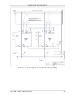
Страница 26: ...LECTRONIC INDUSTRIES LTD Centric 3x480 Vac Installation Guide rel 2 2 20 Figure 13 Recommended connections for 3 wire Gnd config no Neutral For recommended circuit breaker and fuse ratings see Table 5...

Страница 27: ...NIC INDUSTRIES LTD Centric 3x480 Vac Installation Guide rel 2 2 21 Figure 14 Connections for 3 wire Gnd config no Neutral with input isol xformer For recommended circuit breaker and fuse ratings see T...

Страница 28: ...GAMATRONIC ELECTRONIC INDUSTRIES LTD Centric 3x480 Vac Installation Guide rel 2 2 22 Table 5 Maximum input currents for Centric 3x480 Vac...

Страница 29: ...ed circuit breaker switch ratings for Centric 3x480 Vac Note 1 Switch and CB values are based on 10 minute backup time with full load If longer backup is required please consult with your dealer Note...

Страница 30: ...sired 5 Measure the dc voltage at the main terminals of the battery cabinets Verify that you obtain values of at least 240 Vdc for each battery cabinet or at least 480 Vdc across the main battery CB 6...

Страница 31: ...w the battery can be connected to the UPS This example includes two circuit breakers one for each battery cabinet Fuses F1 through F4 have the same value as specified in Table 7 The rating of Fuses F5...

Страница 32: ...attery bus bars on lower front of UPS Table 8 Key to Figure 17 ITEM DESCRIPTION 1 Positive battery bus bar 2 Negative battery bus bar 3 Front door of the UPS cabinet Note The battery Neutral line is t...

Страница 33: ...ONIC ELECTRONIC INDUSTRIES LTD Centric 3x480 Vac Installation Guide rel 2 2 27 Figure 18 Recommended battery cable entry The recommended battery cable entry is from the bottom rear of the UPS See Figu...

Страница 34: ...ATURE ACHIEVABLE PERCENTAGE OF BATTERY S RATED LIFETIME 20 C 100 30 C 50 40 C 25 4 3 5 Cable tray A cable tray is available as an option The cable tray protects the main ac input and output cables and...

Страница 35: ...GAMATRONIC ELECTRONIC INDUSTRIES LTD Centric 3x480 Vac Installation Guide rel 2 2 29 Figure 20 Attaching the lower part of the cable tray Figure 21 The upper part of the cable tray...

Страница 36: ...GAMATRONIC ELECTRONIC INDUSTRIES LTD Centric 3x480 Vac Installation Guide rel 2 2 30 Figure 22 Fastening the upper part of the cable tray Figure 23 Dimensions of the assembled cable tray in mm...

Страница 37: ...4 The Centric s LCD panel should switch ON automatically If the screen is dark it may be that the screen saver is operating Touch the screen to see if the display lights up If not pressing the on off...

Страница 38: ...upply the Centric with required basic configuration information to enable initial operation of the Centric The initial configuration process is described here Figure 24 Initial configuration wizard St...

Страница 39: ...ach choose 2 Then press Next Figure 26 Initial config wizard number of battery sets 4 Indicate the capacity of the connected batteries in ampere hours Ah then press Next This capacity figure is used b...

Страница 40: ...lation Guide rel 2 2 34 5 Scroll through the list to find your time zone select the time zone then press Next Figure 28 Initial config wizard set time zone 6 Press Finish to exit the wizard Figure 29...

Страница 41: ...alarm symbol a red circle is displayed press the alarm symbol to display the potential problems Refer to the troubleshooting section of this document to determine the proper response to the alarm ind...

Страница 42: ...he Main Menu select Setup Connectivity Network Configuration Press the button labeled Obtain an IP address automatically The Centric software obtains an IP address and then reboots itself To assign an...

Страница 43: ...IP Communication with Controller This test is designed to verify that the System Controller is properly configured for communication and that the Web server built into the System Controller is functio...

Страница 44: ...r in what we refer to as connector group 1 connector group 2 and connector group 3 Connector groups 1 and 2 are located on the rear panel of the controller module The controller module is the Centric...

Страница 45: ...2 3 Forced Bypass contacts Normally Open When these contacts are closed the UPS immediately goes into bypass mode These contacts are intended to be used in conjunction with the Maintenance Bypass fun...

Страница 46: ...he external relay changes The output dry contacts enable the Centric to trigger an external circuit in response to a system alarm The connections for the input and output dry contacts are located on t...

Страница 47: ...f EPO manual An external Emergency Power Off EPO switch may be installed on the Centric by the customer The EPO switch cuts power to the load in emergency situations The connection point for the EPO s...

Страница 48: ...opened N O and has two pins The contact is voltage free it can accept up to 250 Vac 10 A 5 5 Surge protector malfunction alarm The Centric 3x480 system is equipped with a MOV type Metal Oxide Varistor...

Страница 49: ...nstalled system Instructions for each type of operation are given below Keep in mind that it is desirable that the number of active dc dc blocks always be equal to or greater than the number of active...

Страница 50: ...ith each module s communication cables attached the UPS modules start up automatically It takes a few minutes for each module to start up You can follow the process by selecting Status Modules DC and...

Страница 51: ...pe M5 conical one on the left and one on the right of the module face 240 kW model 120 kW model Figure 39 Location of the UPS modules in the 240 kW and 120 kW models Table 12 Key to Figure 39 ITEM DES...

Страница 52: ...load UPS will transfer to bypass Continue If the batteries have a good charge you can ignore this message and tap Continue If you think your batteries might not be able to support the load at this tim...

Страница 53: ...odule and adjust the problematic phases up or down as required 1 3 Return to step 1 and repeat the verification and adjustment process until the output voltage of each phase of the replacement module...

Страница 54: ...main menu choose Operation Turn on off Modules off 3 On the screen choose the module to be replaced The modules are numbered from bottom to top The outline of the module you choose becomes highlighte...

Страница 55: ...ear connectors 11 There is a flat cable ribbon cable on the front right and left of the shelf Connect these two flat cables to the UPS module 12 Now push the replacement module all the way into the mo...

Страница 56: ...ltage of one or more phases is not within 2 of the system nominal output voltage then 15 1 Navigate to Setup Modules Ac output voltage adjustment 15 2 Select the replacement module and adjust the prob...

Страница 57: ...type Increase the maximum capacity of the system by 30 kW times the number of modules added For example if you added one module to a 180 kW system you would choose 210 kW as the new system type see Fi...

Страница 58: ...w many of the modules are intended to provide redundancy The Centric User Guide provides more information on redundancy A password is required to perform this function If you do not have the required...

Страница 59: ...the UPS frame with two screws type M5 conical one on the left and one on the right of the module face 20 Navigate to Setup System Nominal Settings and tap the Confirm button 21 Navigate to Operation T...

Страница 60: ...ltage of one or more phases is not within 2 of the system nominal output voltage then 22 1 Navigate to Setup Modules Ac output voltage adjustment 22 2 Select the replacement module and adjust the prob...

Страница 61: ...e the new capacity of the system by multiplying the remaining number of modules by 30 kW For example if you remove one module from a 240 kW system 8 modules you have 7 modules left and should choose 2...

Страница 62: ...number of modules as required and indicate how many of the modules are intended to provide redundancy The Centric User Guide provides more information on redundancy A password is required to perform t...

Страница 63: ...on 7 To verify that the module has been shut down navigate to the module status screen Main screen Status Modules press on the icon of the module you just shut down and verify that the status is OFF f...

Страница 64: ...ctors from the UPS 11 Disconnect the flat cables ribbon cables from the right and left sides of the module s front panel 12 Now remove the UPS module entirely Two persons are required to remove the mo...

Страница 65: ...as only one button the Alarm Off button which enables you to temporarily silence the audible alarm Figure 61 The remote monitoring panel Table 13 LEDs on the remote monitoring panel LED INDICATOR COLO...

Страница 66: ...GAMATRONIC ELECTRONIC INDUSTRIES LTD Centric 3x480 Vac Installation Guide rel 2 2 60 Figure 62 Connecting the remote monitoring panel...

Страница 67: ...thermal tripping and magnetic tripping Circuit breakers can have one or both of these tripping characteristics Magnetic tripping is activated immediately when the current though the circuit breaker ex...

Страница 68: ...ose to use a time delay circuit breaker on the bypass input line recommended rating of the breaker is approximately six times the maximum bypass input current When using a circuit breaker with delayed...

Страница 69: ...up process This is transparent to the system operator 9 1 1 Decentralized static switch method Every Centric UPS is equipped with a static switch to ensure that the UPS will continue to supply power...

Страница 70: ...tors on each end Parallel communication keeps the parallel units synchronized with each other and is used to pass commands and status information between units Each Centric UPS has two D25 parallel co...

Страница 71: ...tric 480 UPS s are being operated in parallel configuration Note that all parallel communication cables the 25 pin cables must be housed in appropriate conduits 9 1 2 1 EPO AND PARALLEL OPERATION An E...

Страница 72: ...communication between UPSs DESCRIPTION QUANTITY GAMATRONIC CATALOG NO 25 pins 5 meter cable 1 GPIN25350 25 pins 10 meter cable 1 GPIN25410 The supplied parallel communication cables are either 5 or 1...

Страница 73: ...d on together Wait until they finish start up and verify that each system is in Normal mode and has no active alarms 8 Put the slave systems in multisystem mode Main menu Setup System Multisystem mode...

Страница 74: ...ach system in bypass mode Main menu Operation Transfer Transfer load to bypass 11 For each slave system compare the output voltage of each phase to that of the master system as you did above except th...

Страница 75: ...GAMATRONIC ELECTRONIC INDUSTRIES LTD Centric 3x480 Vac Installation Guide rel 2 2 69 Figure 71 Connection diagram for 2 parallel units with neutral line...

Страница 76: ...GAMATRONIC ELECTRONIC INDUSTRIES LTD Centric 3x480 Vac Installation Guide rel 2 2 70 Figure 72 Connection diagram for 3 parallel units with neutral line...

Страница 77: ...GAMATRONIC ELECTRONIC INDUSTRIES LTD Centric 3x480 Vac Installation Guide rel 2 2 71 Figure 73 Connection diagram for 4 parallel Centric units with neutral line...

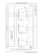
Страница 78: ...GAMATRONIC ELECTRONIC INDUSTRIES LTD Centric 3x480 Vac Installation Guide rel 2 2 72 Figure 74 Connection diagram for 2 parallel units w o neutral line...

Страница 79: ...GAMATRONIC ELECTRONIC INDUSTRIES LTD Centric 3x480 Vac Installation Guide rel 2 2 73 Figure 75 Connection diagram for 3 parallel units w o neutral line...

Страница 80: ...GAMATRONIC ELECTRONIC INDUSTRIES LTD Centric 3x480 Vac Installation Guide rel 2 2 74 Figure 76 Connection diagram for 4 parallel Centric units w o neutral line...

Страница 81: ...ly of power to the loads The maintenance bypass switch routs the current around the UPSs for the safety of the technician The optional maintenance bypass switch is shown in the connection schematics f...

Страница 82: ...ed by an Automatic Transfer Switch ATS Because these two sources are not usually synchronized switching between them requires an interval of at least 10 seconds Figure 77 illustrates the timing factor...

Страница 83: ...le R is the reserve source The timing variables T1 through T5 are described in Figure 77 The knob at the bottom of the control panel controls the actions of the ATS The ATS can be set to use the norma...

Страница 84: ...s should include a visual inspection of the UPS and its batteries and the tightening of any screws and bolts that have over time become loosened The owner of the UPS is responsible for ensuring that t...

Страница 85: ...al and physical condition The operation of the UPS and its batteries conform to design specifications The UPS and batteries are in compliance with all relevant safety standards and regulations It is r...

Страница 86: ...__________________________________________ 3 Environmental Inspection Environmental temperature ________ C Ventilation OK Not OK Air conditioning Yes No Comments ______________________________________...

Страница 87: ...a constant stable load Measured value ____ Vac Measure the voltage between Neutral and Ground at the bypass input The value should be no greater than 5 Vac Use a calibrated voltmeter to measure the re...

Страница 88: ...ngs x 30 Use a power resistor of 0 5 300 W rating recommended for the load to check the voltage drop across the terminals of each battery The voltage measured across the resistor should be no less tha...

Страница 89: ...pare parts dedicated to the service and repair of our products When service is required it will be performed either at the customer s site or in one of our laboratories according to the judgment of ou...

Страница 90: ...Overload withstand Inverter mode 110 10 min 125 60 s 150 30 s Bypass mode 125 10 min 1000 1 cycle Waveform Sinusoidal THD Linear load 2 non linear load 6 Load CF max 6 1 Ac ac efficiency nominal Up t...

Страница 91: ...bypass Battery test failure Over under temperature Overload Each system alarm type can be routed to the dry contact of your choice Communication ports Serial Ethernet USB Communication protocols RS23...

Страница 92: ...Systems Power systems for Telecom Dc to Ac Inverters Dc to Dc Converters Frequency Converters Battery Chargers Power Management Solutions Headquarters and Factory 17 Professor Hartom Street POB 45029...

Отзывы: