


Revision 14
44
August 02, 2019
3.4.5.4 Connect the Computer and the Analyzer
Once the settings are correctly set, press the
OK
button to close the
Communications Setup
dialog box and press the
Logon
button (Figure 3-13)
on the button bar
to connect the computer
to the analyzer.
Figure 3-13
: Logon Button
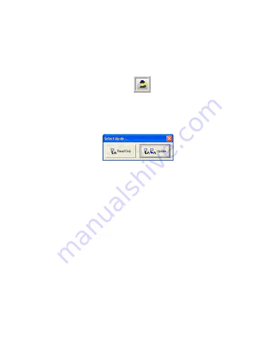
After the
Logon
button is pressed, an information line with increasing length will appear on
the screen. When the logon process is complete, the GUI will present a dialog box (Figure
3-14) asking if the operator wants to enter
Read-Only
or
Update
mode.
Figure 3-14: Select Mode Dialog Box
Read Only
mode does not allow the operator to write any changes to the analyzer. It allows
the operator to view all aspects of the application program and review all the settings of the
analyzer, but prevents the operator from writing any changes to these settings.
Update
mode allows the operator to make changes to settings in the application program and
write these changes to the analyzer. This mode is password protected to prevent
unauthorized changes to the analyzer. The password for the
Update
Mode is set by default to
2222
and can
be changed as described in Section 5.2.1.
If the operator has logged into the analyzer in
Read Only
mode, it is possible to enter
Update
mode by going to the
Tools
menu and selecting
Update
to present the
Password Request
dialog box. If the correct password is entered, the application program will then be in
Update
mode.
If communication is unsuccessful, ensure that:
a) the correct COM port is chosen
b) the correct baud rate is chosen
c) the cable is securely connected to both the PC and the analyzer
d) the IP address is correct
If changing the baud rate and COM port or the IP address still does not result in a successful
connection, please call Galvanic Applied Sciences’ technical support.
Содержание ProTech903
Страница 2: ......
Страница 96: ...Revision 14 96 August 02 2019 Figure 5 19 Event Log...
Страница 122: ...Revision 14 122 August 02 2019 Figure 5 38 Typical Modicon with Floating Point List...
Страница 124: ...Revision 14 124 August 02 2019 Figure 5 40 Expanded Modbus Nodes...
Страница 167: ...Revision 14 167 August 02 2019 Figure 9 1 DC Power Wiring Diagram Figure 9 2 AC Power Wiring Diagram...
Страница 168: ...Revision 14 168 August 02 2019 Figure 9 3 Total Sulfur Wiring Diagram Figure 9 4 AC DC Power Wiring Diagram...
Страница 169: ...Revision 14 169 August 02 2019 Figure 9 5 Solenoid Drivers Wiring Diagram Figure 9 6 Relays Wiring Diagram...
Страница 173: ...Revision 14 173 August 02 2019 Figure 9 13 Isolated RS 485 Port Figure 9 14 P17 RS232 Port to Ethernet Cable...
Страница 175: ...Revision 14 175 August 02 2019 Figure 9 17 Non Isolated 4 20 mA Inputs...
Страница 190: ...Revision 14 190 August 02 2019...


