- 9 -
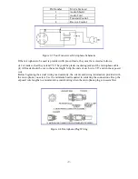
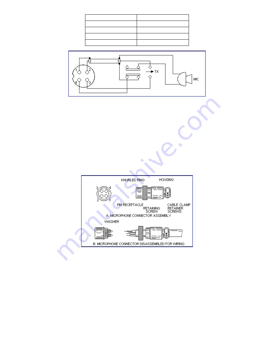
Pin Number
Mic Cable Lead
1
Audio
Shield
2
Audio
Lead
3
Transmit
Control
4
Receive
Control
Figure 2-3 Your Transceiver Microphone Schematic
If the microphone to be used is provided with pre-cut leads, they must be revised as follows :
(i) Cut leads so that they extend 7/16” beyond the plastic insulating jacket of the microphone cable.
(ii) All leads should be cut to the same length. Strip the ends of each wire 1/8” and tin the exposed
wire.
Before beginning the actual wiring read carefully, the circuit and wiring information provided with
the microphone you select. Use the minimum head required in soldering the connections. Keep the
exposed wire lengths to a minimum to avoid shorting when the microphone plug is reassembled.
Figure 2-4 Microphone Plug Wiring
Содержание DX 949
Страница 1: ......
Страница 13: ...12 DX 949 CIRCUIT DIAGRAM...
Страница 14: ...13 CHAPTER 4...
Страница 18: ...17 Figure 4 2 Receiver test setup...
Страница 19: ...18 Figure 4 3 Main PCB Adjustment Locations CHAPTER 5...
Страница 23: ...22...
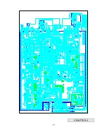
Страница 29: ...28 DX 949 MAIN PCB REMARK SOLDER SIDE WHITE...
Страница 33: ...32...
Страница 34: ...33 AT0949040A...
Страница 35: ...34...


