GS2200M Starter Kit Board Hardware User Guide
GS2200M Starter Kit Board Pinouts
44
GS2K-SKB-HW-UG-001278, Release 1.0
B.1.3 GS2200M UART Connector Pinouts
The UART peripheral connector (J6) is a Pmod™ Type 4-compatible interface. It supports
attaching a peripheral or a host device via a UART interface. Either UART0 or UART1 in
the GS2200M may be routed to the connector, as configured via jumper settings on header
J18.
- UART0 routed to USB port / UART1 routed to peripheral connectors for host mode
- UART0 routed to USB port / UART1 routed to peripheral connectors for peripheral mode
- UART0 routed to peripheral connectors for peripheral mode / UART1 routed to USB port
Alternatively, either UART can be left unconnected by omitting jumpers for that port.
The USB port is always configured for peripheral mode such that the board will always be
a peripheral to the host PC it is connected to.
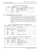
Table 14 SPI Connector Pin Assignments - SKB
Pin No.
Signal Name
Description
1
SS
Slave Select (GPIO33/SDIO_DAT3/SPI0_CSn_0)
2
MOSI
GPIO36/SPI0_DOUTGS2200M is SPI Master Out, Jumper J20 3-4
GPIO34/SPI0_DINGS2200M is SPI Slave In, Jumper J20 2-4
3
MISO
GPIO34/SPI0_DIN GS2200M is SPI Master In, Jumper J20 1-2
GPIO36/SPI0_DOUT GS2200M is SPI Slave Out, Jumper J20 1-3
4
SCK
Serial Clock (GPIO35/SDIO_CLK_CPI0_CLK)
5
GND
Ground
6
VSN
VCC
7
INT
Interrupt Signal from Slave to Master (GPIO37/SDIO_DAT1_INT)
8
RST_N
RESET for Master to reset Slave (GPIO28/I2C_DATA, Low True)
9
ALM_N
Not Specified
10
IO31
Not Specified
11
GND
Ground
12
VSN
VCC
Содержание GS2200M
Страница 3: ...Release 1 0 11 23 2016 Copyright 2016 GainSpan All rights reserved ...
Страница 4: ......
Страница 5: ...Release 1 0 11 23 2016 Copyright 2016 GainSpan All rights reserved ...
Страница 6: ......
Страница 8: ...GS2200M Starter Kit Board Hardware User Guide 8 GS2K SKB HW UG 001278 Release 1 0 ...


