23
INST
INST
INST
INST
INSTALLA
ALLA
ALLA
ALLA
ALLATION - COMBISTREAM & COMBI 65 6
TION - COMBISTREAM & COMBI 65 6
TION - COMBISTREAM & COMBI 65 6
TION - COMBISTREAM & COMBI 65 6
TION - COMBISTREAM & COMBI 65 6
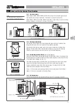
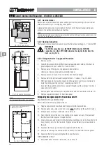
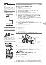
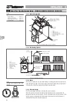
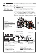
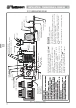
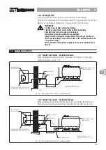
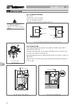
6-2.1 Accumulator
(supplied with Combistream Only)
The Accumulator may be installed at any convenient location within the dwelling,
outhouse, garage, loft or basement.
In normal circumstances the Accumulator should be installed vertically. Where this is
not possible it can be installed horizontally by supporting it in a cradle and ensuring
provision is made to make it fully drainable.
The floor must give adequate support to the filled Accumulator.
The Accumulator must be protected from frost, particularly when it is sited in a loft,
outhouse or garage.
Note that access is required to the top of the vessel for pumping the pressure and
changing the membrane.
Provision must be made to enable the Accumulator to be drained when required.
IMPORTANT
The Accumulator is supplied at 2 Bar pressure. It is recommended to set
the air charge pressure at 1 - 1.5 Bar below the mains pressure -
minimum 0.5 Bar. The system has a pressure reducing valve set at 3 Bar,
therefore the maximum charge pressure should be 2 Bar.
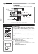
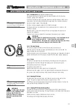
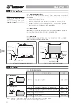
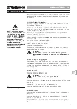
6-2.2 Pressure Gauge
The pressure gauge is provided to indicate the heating system pressure.
When the system is full with cold water and all radiators are full, on and vented, the
gauge will show the cold fill pressure.
Set the red pointer to the cold fill pressure. If the system pressure, indicated by the black
pointer, falls below the cold fill pressure, it means that the system requires topping up.
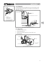
6-2.3 Pump
The pump is a standard 3 speed central heating circulating pump which pumps the
heated water from the Boiler through the heating system and hot water system.
Normally the pump will be set at speed 2.
The pump is wired so that it is:-
ON at all times when the control system is set for heating ON.
ON when the control system is set for hot water ON and the temperature of the water in
the cylinder is less than the setting of the hot water thermostat control setting.
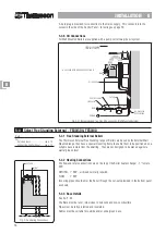
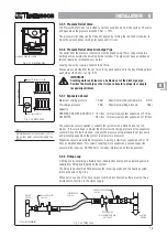
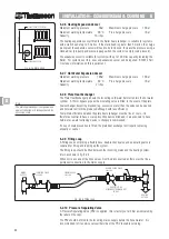
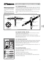
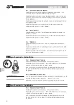
6-2.4 Heating TPR Valve
The temperature pressure relief valve is provided to vent excess pressure from the
system. The valve will open when the pressure exceeds 3 Bar ± 10%.
The TPR valve can be manually opened by turning the red knob clockwise, to close the
valve continue turning clockwise until it clicks.
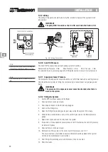
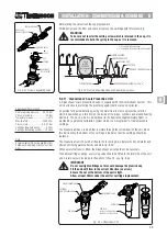
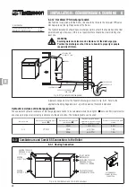
6-2.5 Heating TPR Valve Discharge Pipe
The outlet from the heating TPR valve must be piped using 15mm copper pipe to a
visible position outside the dwelling. The pipe must have a continuous fall and ideally be
terminated over a drain.
Local by-laws may require a Tundish to be fitted - see note.
The vent pipe exits through the back panel of the Boiler.
6-2
Combistream System and Combi 65 Components
2
bar
1
3
4
0
Note
No other pump should be fitted to the
system.
Note
One Tundish is supplied with the Boiler,
this should be fitted to the hot water TPR
discharge, see 6-2.12.
Note
As Combistream is a sealed system, the
pressure at the taps is not affected by the
height of the cold water storage.
IMPORTANT
Scalding water and steam
can be emitted from the
discharge pipe. Position the
discharge so there is no hazard to
property or people (especially
children).
66666
0
1
2
3
4
5
6
0
20
40
60
80
bar
psi

