background image


Page 

 19                                                                                                                                                            


6


T

IPS AND ASSISTANCE 


Frequently Asked Questions (FAQ)  
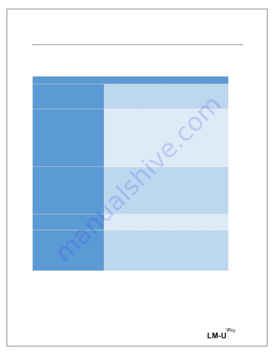
Table 6 FAQ


Question 

 Possible Cause/ Solution 

LCD Display is blank. 


Please check whether the LCD display is Auto off in 
batch Configuration. 


Batteries are low or dry. 

Display show “

o

vr


If Sensor input is more than specified range which 

is given in Table 1, display can show “

o

vr” (

Over the 

range). 


Sensor is not inserted. 


Wrong  Sensor  type  selection  during  batch 
configuration. 


Sensor wire broken. 

Display show “

u

dr


If Sensor input is less than specified range which is 

given in Table 1, display can show “

u

dr” (

Under the 

range). 


Sensor is not inserted. 


Wrong  Sensor  type  select  during  batch 
configuration. 


 Sensor wire broken. 

Device  does  not  Connect  in 
Application. 


Micro USB data Cable not working. 

What change is required for 
4- 20 / 0-20 mA sensor input? 


For 4-20mA, 0-20mA sensor input, make DIP 

switch near sensor connector in “ON” position to 

get internal resistance 50 

Ω.


If another sensor type is selected, then DIP switch 

must be in “OFF” 

position. 

Содержание LM-U PRO Series

Страница 1: ......

Страница 2: ...USE 5 2 3 TECHNICAL DATA 6 3 PRODUCT DESCRIPTION 9 3 1 STATUS LEDS 9 3 2 DISPLAY LCD 9 3 3 KEY FUNCTIONS 10 3 4 SENSOR CONNECTIONS 11 3 5 IMPORTANT INFORMATION AND GLOSSARY OF TERMS 12 4 USING THE PR...

Страница 3: ...Figure 5 Batch Configuration of the Data logger 12 Figure 6 Current Temperature Reading of the LM U Pro Data logger 15 Figure 7 Downloaded data Summary 16 List of Tables Table 1 Specification 6 Table...

Страница 4: ...use the product if there are signs of damage to the housing Carry out only the maintenance and repair work on this instrument that is described in the documentation Follow the prescribed steps exactly...

Страница 5: ...ly and the device be examined If the device is found damaged it should not be operated and the local representative contacted for instructions Ensure that all accessories and documentation is removed...

Страница 6: ...subject to cold chain requirements User can fully configure parameters like Start delay alarm high low limit sensor type temperature unit store interval etc User can also set the information like use...

Страница 7: ...Alarm high low Condition Reading Types Actual with Min Max ON Display and PC Analog Input Details No of Inputs 1 Sensor Input Type Types J K R S T RTD PT 100 DIN43760 0 00385 Vdc 0 1V mA 4 20mA 0 20mA...

Страница 8: ...provides information on the remaining lifetime Battery Reverse Polarity Protected General Restore Calibration User can revert to original factory calibration any time Reusability Yes Online Feature Po...

Страница 9: ...Page 8 Sensor Range RTD Pt 100 100 to 600 C 4 20mA 1999 0 20mA 1999 0 1V 1999 J type TC 0 to 400 C K type TC 0 to 1200 C R type TC 0 to 1700 C S type TC 0 to 1700 C T type TC 100 to 400 C...

Страница 10: ...er limit value exceeded Note For Technical reasons the display intensity of liquid crystal display becomes lower at temperatures below 0 C This has no influence on the measuring accuracy For technical...

Страница 11: ...og the data TAG at that instance of time if batch is running Display will Show tAg Continue to press the key for more than 8 seconds and if batch is running batch will stop and display will show StP T...

Страница 12: ...sor Connection Table Sensor Input 1 2 3 4 RTD Red White White Common White Common Volt Not connected Not connected mV Not connected Not connected 0 20 4 20 mA Not connected Not connected Note 1 Verify...

Страница 13: ...set point values for the individual alarm high low trigger 4 Unit of Temperature The unit for temperature is C 5 Sensor Type User can select the required sensor input refer the table 4 from the optio...

Страница 14: ...s current date and time of the data logger Click on the clock button to sync the current date and time of the device with PC time as per selected time zone 13 Start Time It is the time at which Batch...

Страница 15: ...running Rec Mode user can log special event with time stamp by pressing MIN MAX TAG key for more than 4 seconds Display will show tAg Each TAG is considered as one record User can place as many TAGS a...

Страница 16: ...t data report Connect the data logger to Windows PC via the Micro USB data cable The current temperature reading as per the selected sensor will be seen as shown in the figure 6 Figure 6 Current Tempe...

Страница 17: ...Page 16 Figure 7 Downloaded data Summary...

Страница 18: ...ack of the data logger Take the spent batteries out of the battery compartment Insert new batteries see technical data for type required into the instrument so that the positive Negative pole is visib...

Страница 19: ...accordance with your local regulations Do not expose the Data Logger to extreme temperatures as it may lead to the destruction of the battery and may cause injuries 5 3 CLEANING THE INSTRUMENT If the...

Страница 20: ...selection during batch configuration Sensor wire broken Display show udr If Sensor input is less than specified range which is given in Table 1 display can show udr Under the range Sensor is not inser...

Страница 21: ...7 ORDER CODE Table 7 Order Code Data Logger Sensor Type Pressure Rang Communication Type Software Type Memory Type 6 6X Pro 0 Universal Input 0 No Pressure 3 USB 6 LM View Non Secure 1 Memory 7 LM vie...

Отзывы: