background image


Section 50 


00-02-1031 

2019-08-07 

- 11 -


Before Starting the Equipment for the First Time  

Setup 

– MV-5-C Display 

Read and follow steps in the order listed. 

1.  Locate the system drawing inside the panel and verify its drawing number matches the sticker on the 

lower front panel. 

2.  Locate the legend of the drawing and find the configuration description. Record this description. 

3.  Power up the Centurion System.  

a.  Allow time for the display to boot up and land on the Home Screen / Landing Page, approximately 

15 seconds.  


b.  From the Centurion Home Screen / Landing Page, touch the Arrow key to scroll left until you find 

the screen FW Murphy 

– MVIEW screen.  

c.  Verify that the configuration description matches the one you previously recorded from the 

drawing legend. 


Содержание Centurion C5 M-VIEW MV-5-C

Страница 1: ...00 02 1031 2019 08 07 Section 50 Centurion C5 M VIEW MonochromeLCD MV 5 C OperationsManual...

Страница 2: ...bsite and review our support documentation including Wiring the Murphy Way www fwmurphy com uploaded WIR_Murphy_Way pdf Disconnect all power and be sure machine is inoperative before beginning install...

Страница 3: ...le concentrations For AEx Ex Zone 2 The equipment shall only be used in an area of pollution degree 2 as defined in IEC 60664 1 The equipment shall be installed completely within an enclosure that pro...

Страница 4: ...THIS PAGE INTENTIONALLY LEFT BLANK...

Страница 5: ...play 11 Operational Screens 14 User Configurable Screens 14 Map of Operational Screens 14 FW Murphy Logo Screen 14 Corporate and Configuration Information Screen 15 Bootloader and Firmware Information...

Страница 6: ...er Password Protected 37 Centurion Serial Ports Screen Super User Password Protected 38 Centurion CAN Ports Screen Super User Password Protected 38 Centurion Ethernet Screen Super User Password Protec...

Страница 7: ...d optimize small to medium sized gas operated compressors and pumps in the field Proper operation is maintained by monitoring setpoints and digital analog and temperature input points and providing th...

Страница 8: ...5 1 Controller NOTE The Expansion modules have the same 2 Power LEDs and COP blink codes as the C5 1 They are located next to the power plug on all modules C5 1 Power LED Indicators Power is always tw...

Страница 9: ...ve GREEN LED Flash Unit is receiving data Off No communication active RS232 RS485 CAN bus C5 1 DIP Switch Setting Switch 1 8 Modbus Slave Address function for RS485 2 RS232 2 Selectable 1 253 If set t...

Страница 10: ...ion controller The primary purpose of the display is to view controller operational information view edit controller operational parameters send commands to controller such as stop edit and reset Home...

Страница 11: ...reen Set Up Screen Exit Setup mode Edit Screen Exit without saving changes to the current configuration Fn Function Key Operating Status Screen Enter Function mode and display a dialog box with additi...

Страница 12: ...ase the digit selected by the cursor from 0 to 9 The user will not be allowed to decrease the selected digit if it would result in exceeding range limits Toggle the value in a list of options if editi...

Страница 13: ...e seven 7 lines visible at a time Setup screens have five 5 lines visible at a time Seeing the Up and Down Arrows on the screen indicate that more lines are available on the page Use the Left or Right...

Страница 14: ...lue will exceed range limits the sign may not be allowed to change In this case try reducing the number by decreasing the left most digit by one or more and attempt to change the sign again Press the...

Страница 15: ...g Reset or Run Stop is a Remote function and will change the Mode to Remote if it is in Local FN Screen Pressing the Function Fn key from any Operational screen will display the Function Menu screen m...

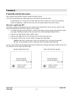
Страница 16: ...or 133 for super 1 To access the password screen anytime from the Home Screen Landing Page press the Setup Enter key to open the Password screen The edit curser rest on the far right digit Example 00...

Страница 17: ...ocate the legend of the drawing and find the configuration description Record this description 3 Power up the Centurion System a Allow time for the display to boot up and land on the Home Screen Landi...

Страница 18: ...Status MVIEW Comm Status Centurion Comm Status Real Time Clock Setup Super User Setup Centurion Serial Ports Centurion Can Ports Centurion Ethernet Centurion EMMC Log MVIEW Serial Ports MVIEW CAN Port...

Страница 19: ...mpleted the Unit State will read Stopping 4 When everything has been recognized as back to normal the Unit State will read Panel Ready Fault Shutdown The Centurion will continually monitor for Fault o...

Страница 20: ...that can be mapped to the Centurion Modbus map and given a label For more information on configuring the optional screens through the Centurion Configuration Tool please refer to the Configuration Too...

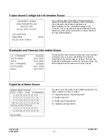
Страница 21: ...checksum and new date timestamp Bootloader and Firmware Information Screen The Bootloader and Firmware Information screen provides information for you to give our FW Murphy Technical Support staff sho...

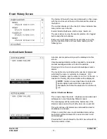
Страница 22: ...he list Each event is displayed with the event label on one line and the real time clock and hour meter reading on the following line Shutdown Snapshot Screen The shutdown snapshot screen is a capture...

Страница 23: ...n this screen will acknowledge all active alarms The top right corner will indicate the number of alarms and which line the cursor is currently on Example 3 10 indicates 10 alarms and the cursor is on...

Страница 24: ...wn arrow icons will appear at the bottom of the screen to indicate the ability to scroll up or down to see additional parameters Custom Control Loop Screen The user may choose to display any configure...

Страница 25: ...on the Centurion Configuration the last page to the right will contain the Compressor Rod Load information The calculated tension and compression forces on the rod are displayed in Imperial or Metric...

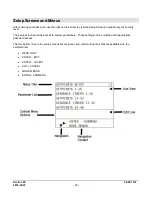
Страница 26: ...s available at your security level The setup screens provide access to system parameters These settings can be modified with appropriate password access The two bottom lines in the setup screens list...

Страница 27: ...larm and shutdown setpoints a user might have configured include High shutdown High High High warning High Low warning Low Low shutdown Low Low To edit a configured setpoint a Select the setpoint grou...

Страница 28: ...he Sx timers begin concurrently with the Bx timers No Flow The global delay used for delaying the triggering of a no flow event This global no flow timer is enabled after B1 expires and begins timing...

Страница 29: ...ube permissive failure however the operation depends on the configuration Maintenance Timer Setup Screen The user may access and edit the ten 10 maintenance duration presets and time remaining setting...

Страница 30: ...tput pulses c 4 Step Load turns on 4 digital outputs in a 4 step staggered loading scheme with time delays in between the loading steps The ultimate goal of the loop is to reduce the error to zero whi...

Страница 31: ...ed when there is a configuration for overriding the control loop with another process variable Each control loop may have up to 3 control loop override settings based on setpoint or digital inputs sig...

Страница 32: ...me between pulses This should be set long enough to allow the results of the previous pulse to have effect on the process before a new pulse is generated 4 Inc Dec Xover On Time 1 20s Set the fixed on...

Страница 33: ...udes an Overcrank event it will be triggered by this signal Motor Define a value for number of motor start attempts per hour after Short cycle which an excess start attempts will be triggered in the s...

Страница 34: ...ll be recognized and accepted as ON or OFF by the sequence If the input does not remain ON or OFF for the duration of the delay the timer will reset d Raw Status The actual measured sensor state e Tot...

Страница 35: ...ured digital outputs the user may edit a Action Select normally open or normally closed Normally closed inverts the logic associated with the output if desired b Raw Status The actual output state To...

Страница 36: ...g input change the raw offset and max settings The scaled minimum and maximum settings should match the engineering unit range for the device c Moving Average Samples 1 2 4 Apply averaging filter to t...

Страница 37: ...will be shown for each channel For all configured analog output devices the user may edit a Minimum Minimum output In most cases 0 addresses a typical application 4mA b Maximum Maximum output In most...

Страница 38: ...wire faults that may exist for the sensor c Last Status Error The last detected wire fault for the sensor use this record to troubleshoot intermittent faults this line will hold the last recorded err...

Страница 39: ...Pressure Display for the input channel used as suction pressure for the throw f Discharge Pressure Drop Setpoint in Percent for the pressure drop from the internal cylinder pressures to the measuremen...

Страница 40: ...the active pixels of the display will become darker Increasing the contrast too much may also increase the darkness of the background NOTE This value changes in real time as adjustment are being made...

Страница 41: ...t of relative loading of the communication bus b Receive count total number of received packets c Transmit Count total number of transmitted packets d Frame Errors total number of packets with frame e...

Страница 42: ...ber of transmitted packets d Frame Errors total number of packets with frame errors detected e HW Overruns total number of hardware overruns f MB Exceptions total number of Modbus packets with excepti...

Страница 43: ...ER key to change the Super user Password The current password is displayed and can be changed to any number between 100 and 65535 It cannot be the same as the standard password and cannot be set to ze...

Страница 44: ...Modbus Address Display Set the Modbus RTU slave address for the serial port g 232 1 2 Reply Delay 0 65535mS Optional time delay for the Modbus response h 232 1 2 Baud Rate Select the appropriate tran...

Страница 45: ...t the IP address for the Centurion Gateway View Set the default gateway IP address to be used by the Centurion Netmask View Set the IP network mask for the Centurion Centurion EMMC Log Files Screen Su...

Страница 46: ...ect the appropriate transmission baud rate from these six choices 9600 19200 38400 57600 115200 f 485 1 2 Mode MVIEW CAN Ports Screen Super User Password Protected CANbus is used for long distance hig...

Страница 47: ...hernet Screen Super User Password Protected Future use MVIEW Static Block Screen Super User Password Protected Diagnostic menu for the M View manufacturing information Used by the Factory Mac Address...

Страница 48: ...on CAN 1 CAN 2 shared terminal block CAN 1 uses HI 1 LO 1 and common SHD shield CAN 2 Not Used Downloading Configurations and Firmware Updates The Centurion controller and display are configured and u...

Страница 49: ...ut Terminals 18 to 29 are analog inputs on the Centurion Main I O module Accepts voltage signals within the range of 0 to 5 VDC or 0 to 24 mA and are compared to controller setpoints and or displayed...

Страница 50: ...g of a device that changes resistance according to temperature Signal An electrical quantity of voltage or current that is used to represent or signify some other physical quantity such as the state o...

Страница 51: ...Section 50 00 02 1031 2019 08 07 45 NOTES...

Страница 52: ......

Отзывы: