background image

&

2

'

(

1

2

7

<

3

(

63

,

7

(

0

1

2

1

$

0

(

2

)

3

3

$

5

7

2

8

7

/

,

1

(

'

:

*

1

2

2

5

3

(

5

6

6

(

7

3

(

5

9

9

(

6

6

3

$

5

(

:

2

5

.

,

1

*

4

8

$

1

7

,

7

<

5

(

0

$

5

.

6

&

2

'

(

1

2

%

2

;

1

2

3

6

+

,

3

1

2

6

3

$

5

(

3

$

5

7

6

/

,

6

7

)

2

5

8

6

(

6

(

7

6

3

(

5

9

9

(

6

6

(

/

7

<

3

(

1

2

+-;

㺩㺋㺎㺛㺼

)*%2$9

$3%)

*/$6678%(

)86(

0

)

5

6

1

$

0

(

)

8

58

1

2

(

/

(

&

75

,

&

&

2

/7

'

'

:

*

1

2

'

,

0

(

1

6

,

2

1

6

,

1

'

5

$

:

,

1

*

)

2

5

5

(

)

(

5

(

1

&

(

2

1

/

<

&3&

A

-13

Содержание FR-1908V-BB

Страница 1: ...6 3 ADJUSTMENTS 3 1 3 1 How to Open the Protected Menus 3 1 3 2 How to Set Alarms 3 2 3 3 How to Enter Your Ship s Characteristics 3 2 3 4 How to Adjust Sweep Timing 3 3 3 5 How to Adjust Video Level...

Страница 2: ...Installation Manual This page is intentionally left blank...

Страница 3: ...wer cable Do not open the equipment unless totally familiar with electrical circuits and service manual Only qualified personnel should work inside the equipment Construct a suitable service platform...

Страница 4: ...PROCESSOR UNIT RPU 026 Sub Display NMEA1 HEADING SENSOR IEC61162 2 NMEA2 AIS IEC61162 2 NMEA3 NAV EQUIPMENT IEC61162 1 NMEA4 Doppler IEC61162 1 NMEA5 Alarm INS IEC61162 1 NMEA6 ECDIS TTM IEC61162 1 Co...

Страница 5: ...2550 mm 26 rpm Processor Unit RPU 026 1 Control Unit RCU 032 1 Installation Materials CP03 34401 001 194 530 1 For control unit CP03 34501 001 194 550 1 For processor unit CP03 33401 001 107 930 1 Fo...

Страница 6: ...EQUIPMENT LISTS iv This page is intentionally left blank...

Страница 7: ...sible routing the signal cable near other onboard electrical equipment Also avoid running the cable in parallel with a power cable A magnetic compass will be affected if placed too close to the antenn...

Страница 8: ...s for the antenna radiator with anticorrosive adheasive 5 Grease the O ring and set it to the O ring groove of the radiator flange 6 Set the antenna radiator to the radiator bracket 7 Coat hex bolts M...

Страница 9: ...diameter in the mounting platform 3 Lay the rubber mat supplied on the mounting platform 4 Place the antenna unit on the rubber mat orienting the unit so the bow mark on its base faces the ship s bow...

Страница 10: ...it Coat the entire ground system with adhesive supplied 7 Confirm that the hoist rings are removed The ground point must be within 300 mm from the ground termninal on the antenna unit Coat with marine...

Страница 11: ...es subject to water splash and rain Select a mounting location considering the length of the cables connected Leave sufficient space on the sides and rear of the unit to facilitate maintenance See the...

Страница 12: ...unted on the bulkhead 1 Mark location for four self tapping screws if screws will be used 2 Insert four bolts M5 supplied or self tapping screws 5x20 leaving approx 5 mm of the bolts screws exposed 3...

Страница 13: ...r Unit The system is designed with the MU 190V local supply in mind The output video sig nal is in portrait format For configurations with monitors other than the MU 190V con sider the following point...

Страница 14: ...1 MOUNTING 1 8 This page is intentionally left blank...

Страница 15: ...61162 USB mouse ROT 20mV deg Autopilot 20mV deg Rudder 1 100mV deg Pilot function ROT alarm DVI cable 115 230 VAC Rectifier Processor unit RPU 026 USB cable 24 VDC 24 VDC Satellite compass Inland AIS...

Страница 16: ...800 mm length from the cable gland 6 Slide two washers rubber gasket washer and clamping ring onto the cable in that order 7 Fabricate the signal cable as shown in below 1 Remove the vinyl sheath for...

Страница 17: ...mm each Twist shields together and attach crimp on lug FV5 5 4 yellow I4 5 Remove insulation of each core approx 8 mm 8 Fabricate the coaxial cable 9 Pass the shield between the clamping ring and the...

Страница 18: ...onnector Press downward Terminal opener WAGO connector Wire Twist Procedure 1 Twist the core 2 Set terminal opener and press it downward 3 Insert the core into hole 4 Remove the terminal opener 5 Pull...

Страница 19: ...he module in until it stops Tighten the fixing bolts Be sure to push in the transceiver unit until it stops Failure to do so may cause microwave leakage 17 Fasten the shield wire to the wing nut on th...

Страница 20: ...th vinyl tape Lay the section where paint was peeled on the cable clamp on the cable entry side of the processor unit Fasten the cable clamp 6 Fasten the crimp on lugs to the terminal block DVI D and...

Страница 21: ...P9548 inside the processor unit Open the cover of the processor unit to find the board J603 J602 Antenna cable J617 NMEA6 ECDIS J616 NMEA5 INS J613 NMEA2 AIS J615 NMEA4 Doppler J614 NMEA3 Navigator J6...

Страница 22: ...ath 240 Wind the inner shield around the outer shield Vinyl tape Set this part in the cable clamp Connect to WAGO connector Coaxial cable 8 15 515 Conductor Fold back shield Inner shield 100 Fold back...

Страница 23: ...he MENU key five times while pressing the HL OFF key MAIN menu SERVICE MENU INITIALIZE menu MAIN CONFIGURATION menu INSTALLATION menu BRILL menu and CUSTOM menu You can edit and save the settings for...

Страница 24: ...than the above three alarms 1 Press the MENU key to show the main menu 2 Use the touch pad to select 13 INITIALIZE then press the left button click to show the INITIALIZE menu 3 Click ALARM then click...

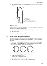
Страница 25: ...ocessor unit Adjust sweep timing at installation to prevent the following symptoms The echo of a straight target for example pier on the 0 25 NM range will appear on the display as being pulled inward...

Страница 26: ...is selected 1 Open the MAIN CONFIGURATION menu 2 Click INSTALLATION to show the INSTALLATION menu 3 Click 3 VIDEO ADJ and AUTO in order to automatically adjust the video level When using the manual a...

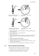
Страница 27: ...ing range is 0 to 359 9 degrees 8 Confirm that the target echo is displayed at the correct bearing on the screen 3 7 How to Suppress Main Bang If main bang appears at the screen center suppress it as...

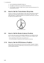
Страница 28: ...NSTALLATION menu and enter the referring to the illustration below 3 9 How to Set the Radar Antenna Position Set the radar antenna position at SCANNER POSITION on the INSTALLATION menu To set the ante...

Страница 29: ...device to test position 6 Click GAIN ADJUST 7 Rotate the setting knob to duplicate the external ROT or Rudder indication on the radar 8 Push the left button Autopilot 1 Set external autopilot to Follo...

Страница 30: ...3 ADJUSTMENTS 3 8 This page is intentionally left blank...

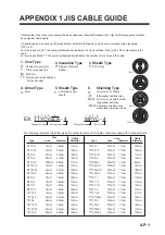
Страница 31: ...CY 4 0 75mm2 1 11mm 17 7mm TTYCY 4S 0 75mm2 1 11mm 21 1mm TTYCY 4SLA 0 75mm2 1 11mm 19 5mm TTYCYS 1 0 75mm2 1 11mm 12 1mm TTYCYS 4 0 75mm2 1 11mm 18 5mm TTYCYSLA 1 0 75mm2 1 11mm 11 2mm TTYCYSLA 4 0 7...

Страница 32: ...OFF ON ALARM SOUND LEVEL OFF LOW MID HIGH SENSOR ERROR OFF ON AIS ALARM OFF ON OTHER WARNING OFF ON GRAPH ON OFF OFFSET ADJUST GAIN ADJUST 300 0 to 300 0 0 0 GRAPH ON OFF OFFSET ADJUST GAIN ADJUST 180...

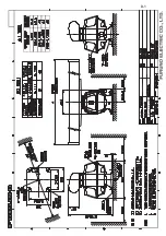
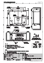
Страница 33: ...ALLATION MATERIALS CP03 19101 008 487 130 1 DIMENSIONS IN DRAWING FOR REFERENCE ONLY A 1 C3464 Z04 A 03FS X 9856 0 XN24AF N A M E O U T L I N E DESCRIPTION CODE Q TY 1 1 UNIT ANTENNA XN24AF 008 487 12...

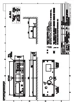
Страница 34: ...5 3 576 63 167 7 21 0 7 5 6 167 7 21 0 7 5 6 3 C3584 Z01 D A 3 5 8 538 1 0 2 8 7 1 6 5 37 21 2 4 7 81 7 352 6625 81 7 538 21752 81 7 5 8 63 5 3 576 63 5 3 576 63 167 7 21 0 7 5 6 167 7 21 0 7 5 6 3 1...

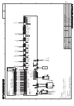
Страница 35: ...7 81 7 352 6625 81 7 538 63 5 3 576 63 5 3 576 63 167 7 21 0 7 5 6 167 7 21 0 7 5 6 3 2 80 17 23 5 725 6 0 18 1 20 167 7 21 0 18 1 0 A 5 5 8 1 0 2 8 7 1 6 5 37 21 2 4 7 81 7 21752 81 7 5 8 167 7 21 0...

Страница 36: ...7 1 01 6 2 2 176 0 0 3 6 4 4 5 01 5 4 26 105 056 6 10 6 4 5 45 14415 10 2411 47 4 41 5 1 01 5 9 5 4 41 5 1 01 4 2 10 7 8 1 01 10 076 575 1 01 6 9 5 4 575 1 01 524 0 9 5 4 575 1 01 10 5 4 9 575 1 01 10...

Страница 37: ...5 0 4 9 0 14 4 4 0 10 691 6 2 5 0 1 5 56 14 0 6 6 19 4 241 7 6 5 22 0 2 1 6 722 4 241 7 6 37 6 5 6 5 A 9 1 01 6 2 2 176 0 0 3 6 4 4 5 01 5 4 26 105 056 6 10 6 4 5 5 6 22 0 5 4 9 575 1 01 05 105 0 4 9...

Страница 38: ...691 6 2 5 0 1 5 56 14 0 6 6 19 4 241 7 6 5 22 0 2 1 6 722 4 241 7 6 37 6 5 6 5 A 11 2 12 7 3 63 7 0 12 1 0 2 3 3 57 287 1 12 25 3 5 6 6 7 3 5 9 9 6 63 5 25 1 48 17 7 5 0 5 6 2 12 2 12 3 6 3 12 63 5 3...

Страница 39: ...0 12 1 0 2 3 3 57 287 1 12 25 3 5 6 6 7 3 5 9 9 6 63 5 25 1 48 17 7 5 0 5 6 2 12 2 12 3 6 3 12 63 5 3 576 67 25 8 6 6 76 3 5 9 9 66 7 3 12 2 9 3 66 78 86 0 5 6 1 0 85812 75 2 7 12 0 16 216 1 5 1 25 5...

Страница 40: ...11 Dec 2018 H MAKI D 1...

Страница 41: ...D 2 2 Nov 2017 H MAKI...

Страница 42: ...D 3 2 Nov 2017 H MAKI...

Страница 43: ...5 5 29 5 5 9 5 5 5 17 5 211 7 21 5 0 9 2B 1 1 96 51 5 51 5 51 33 7 25 5 25 8 33 5 51 7 8 51 5 25 8 51 5 5 0 P 352 6625 81 7 538 7 9 1 3 B 3 B 7 B75 1 1 3 9 0 9 3 30B 20021 30B7 5 30B7 5 1 1 781 1 B 1...

Страница 44: ...is elemental chlorine free FURUNO Authorized Distributor Dealer 9 52 Ashihara cho Nishinomiya 662 8580 JAPAN A JAN 2018 Printed in Japan All rights reserved B DEC 12 2018 Pub No IME 36700 B TEHI FR 1...

Отзывы: