


5. CALIBRATION
5-13
5
14. Click the [OK] (or [Apply]) button on the [Calibration Setting] window to apply the
measured calibration values (or manually input [Theory TS] and [Calibration Val-
ue] to the unit.
Note:
If the [Stop] button is clicked at step 13, the message "Restarting calibration.
Start from the last quit point?" appears the next time you click the [Measure] button on
the [Calibration Setting] window. Click the [Yes] or [No] button.
5.4.2
Operations available during the measurement
The following operations are available during the measurement.
• Switch between the calibration display and the directivity display.
• Switch to the [Progress Details] window.
• Set the calibration extraction area.
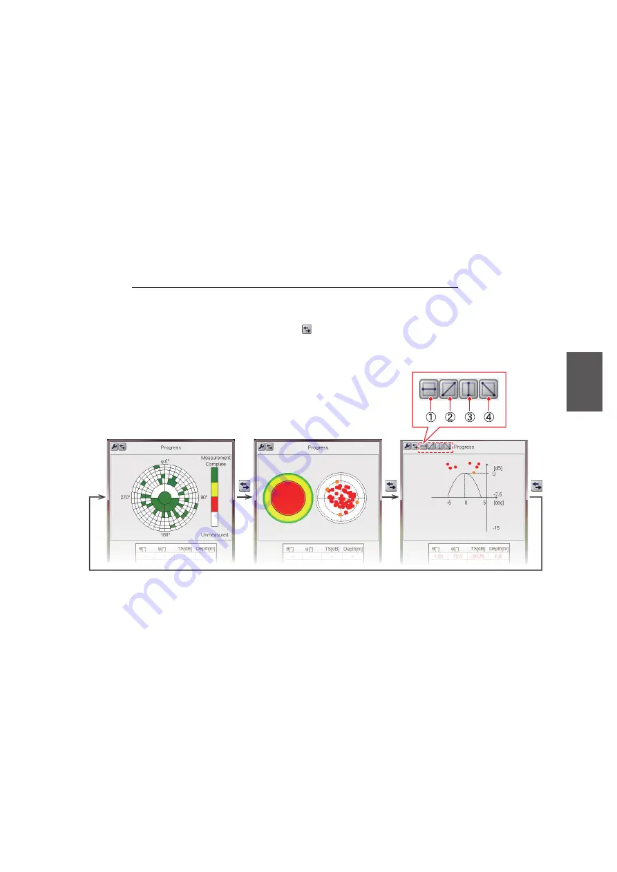
Switch between calibration display and directivity display
You can switch between the calibration display and the directivity display (2D, 1D).
Click the [Display Switch] button ( ) on the [Progress] window. Each click changes
the display in the sequence shown below.
•
2D display
: Information obtained during calibration is color-coded by section and
plotted with circles.
•
1D display
: The horizontal axis directional angle (deg) and directional characteristic
value (dB) shown for a specific section*.
* The direction can be switched with the buttons on the above window ((1) 90° to
270°, (2) 135° to 315°, (3) 0° to 180°, (4) 45° to 225°).
Calibration display
Directivity display (2D)
Directivity display (1D)


