1. MOUNTING
1-2
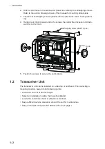
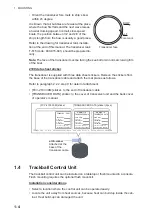
2. Drill four pilot holes in the bulkhead or panel on a tabletop for self-tapping screws.
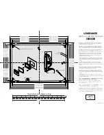
Refer to the outline drawing at back of this manual for mounting dimensions.
3. Fasten four self-tapping screws (
I
6x20) into the pilot holes, leave 5 mm protrud-
ing.
4. Hang (or set) the processor unit to the screws, then slide the processor unit down-
ward (or to the front).
5. Fasten the screws to secure the unit in place.
1.2
Transceiver Unit
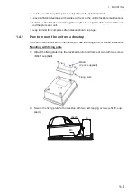
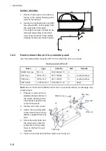
The transceiver unit can be installed on a tabletop or bulkhead. When selecting a
mounting location, keep in mind following points:
• Locate the unit out of direct sunlight.
• Select an installation location that is well ventilated.
• Locate the unit where shock or vibration is minimal.
• Keep sufficient service clearance around the unit for maintenance.
• Keep in mind the compass safe distance shown on page i.
Washer
Self-tapping screw (
φ
6x20, 4 pcs.)
Knob
5
Содержание FCV-2100
Страница 6: ...EQUIPMENT LISTS iv This page is intentionally left blank...
Страница 14: ...1 MOUNTING 1 8 This page is intentionally left blank...
Страница 46: ...3 INITIAL SETTINGS 3 18 This page is intentionally left blank...
Страница 52: ...16 Nov 2015 H MAKI 16 Nov 2015 H MAKI...
Страница 53: ...17 Nov 2015 H MAKI 17 Nov 2015 H MAKI...
Страница 54: ...26 Feb 2016 H MAKI 26 Feb 2016 H MAKI...
Страница 55: ...17 Nov 2011 Y NISHIYAMA 17 Nov 2011 Y NISHIYAMA...
Страница 56: ...17 Nov 2011 Y NISHIYAMA 17 Nov 2011 Y NISHIYAMA...
Страница 57: ...17 Nov 2011 Y NISHIYAMA 17 Nov 2011 Y NISHIYAMA...
Страница 58: ...8 Mar 2016 H MAKI...

