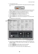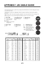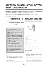
2. WIRING
15
2.4
Net Sonde
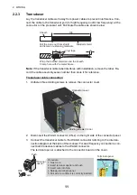
Connect the net sonde FNZ-18 or FNZ-28 to the WAGO connector CN-6 in the con-
nector box in the processor unit. Connect the net sonde to the display unit with a
TTYCSLA-4 cable. The following procedure shows how to connect the cables from the
net sonde to the processor unit.
1. Fabricate the TTYCSLA-4 cable ends referring to the figure below.
2. Unfasten three binding screws to remove the cover of the processor unit.
3. Detach the WAGO connector for the net sonde (CN-6),
4. Connect the cable cores to the WAGO connector referring to the interconnection
diagram.
5. Reattach the WAGO connector.
6. Unfasten the screws on the cable clamp, then fix the cables with the cable clamp.
7. Close the cover of the processor unit.
8. Fit a connector to the loose end of the net sonde display’s cable, then connect the
cable to the net sonde display unit.
Note:
When connecting an analog net sonde
signal to the FCV-1900, the net sonde display
unit must be modified. Attach an 820 ohm resis-
tor (±5%, 1/4W or more) in parallel with R36 (1k
ohm) on the MAIN board 11P1118. Fix the resis-
tor on rear side of the board as follows.
Armor
Vinyl sheath
Vinyl tape
Twisted core
Drain wire
250
6
6
15
10
150
Plastic tube
C34 0.01u
CR9 155133
R36 1k
U31
820
䃈
(±0.5%,1/4W
)
KP-H
KP-C
1
2
Rear
Front
R36
Solder the resistor with parallel on R36.
Содержание FCV-1900/B/G
Страница 46: ...D 1 14 Apr 2015 H MAKI...
Страница 47: ...D 2 15 Apr 2015 H MAKI...
Страница 48: ...D 3 15 Jan 2015 H MAKI...
Страница 50: ......
Страница 51: ......

