2. WIRING
2-22
2.5
Monitor Unit
For the wiring of the monitor unit MU-190/231, see the operator’s manual supplied with
the monitor unit. Also, for resolution and image data output settings, see the Instruc-
tion Manual (E42-01204-*).
Mounting consideration
(Standard type)
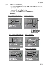
• Connect the radar main monitor to the DVI1 and COM1 ports.
• For the sub radar monitor, connect it to the DVI2 and COM2 port.
(VDR connection)
To connect a VDR, it is necessary to output data in analog format. See the Instruction
Manual (E42-01204-*). When connecting a VDR to the DVI3 port, use the optional
DVI-BNCX5-L2000 cable to output RGB signal from the DVI-I. See the operator’s
manual supplied with the VDR. Adjustment of the output picture is necessary.
Menu Setting
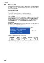
The [INSTALLATION SETTING] menu appears only when the power is turned on for
the first time after installation of the monitor unit.
Adjust the settings referring to the following table.
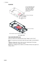
*: [DVI PWR SYNC] is the slide switch at the bottom rear of the monitor unit. Confirm
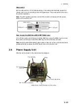
that this switch is set to [ON] (default setting). See Slide switch below for details.
EXT BRILL
CTRL
SERIAL
BAIDRATE
COLOR
CALIBRATION
KEY LOCK
DVI PWR
SYNC*
RS-485
4800bps
ON
ON
ON
INSTALLATION SETTING
EXT BRILL CTRL
SERIAL BAUDRATE
COLOR CALIBRATION
KEY LOCK
SAVE AND EXIT
RS-485
4800bps
ON
ON
YES
(OFF/DVI1/DVI2/RS-232C/RS-485/USB)
(4800/9600/19200/38400)
(OFF/ON)
(OFF/ON)
(NO/YES)
Menu
Menu item
Содержание FCR-2139S-BB
Страница 74: ...2 WIRING 2 48 This page is intentionally left blank ...
Страница 136: ...D 1 14 Feb 2011 Y NISHIYAMA ...
Страница 137: ...D 2 Y Hatai ...
Страница 138: ...May17 07 R Esumi D 3 ...
Страница 139: ...13 Feb 2014 H MAKI D 4 ...
Страница 140: ...D 5 24 May 2012 Y NISHIYAMA ...
Страница 141: ...D 6 24 May 2012 Y NISHIYAMA ...
Страница 142: ...D 7 24 May 2012 Y NISHIYAMA ...
Страница 143: ...D 8 ...
Страница 144: ...D 9 ...
Страница 145: ...D 10 ...
Страница 148: ...13 Jan 2012 Y NISHIYAMA 西山義浩 D 13 ...
Страница 149: ...13 Jan 2012 Y NISHIYAMA D 14 ...
Страница 150: ...D 15 ...

