background image

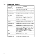
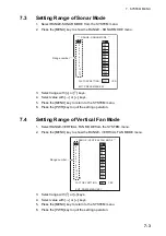
7.  SYSTEM MENU

7-4

7.5

Setting Screen Colors

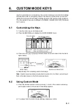
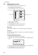
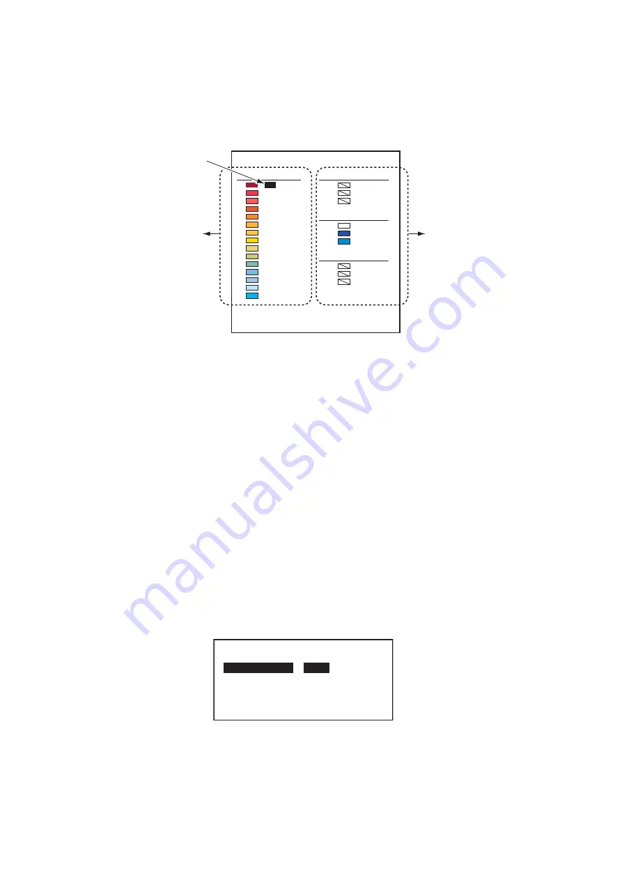
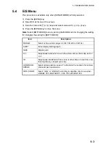
The color setting screen allows you to adjust display colors.

1. Select COLOR from the SYSTEM menu.
2. Press the [MENU] key to show the COLOR menu.

3. Select item with [

] or [

] keys.

4. Select color with [

] or [

] keys.

5. Press the [MENU] key to return to the SYSTEM menu.
6. Press the [PWR] key to quit the setting operation.

Echo color

Echo signal level is indicated (1 to 15). The larger number is the stronger signal.

Hue color

Hue color settings are available in three patterns. They includes the text, background 
and menu frame colors.

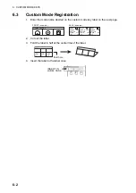
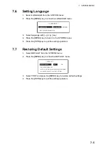
Restoring default setting colors

1. Select FACTORY SETTING from the COLOR menu.
2. Select “YES“ with [

] key and press the [MENU] key. The message window ap-

pears.

3. Select “YES“ with [

] key and press the MENU key to return to the COLOR menu.

4. Press the [MENU] key to return to the SYSTEM menu.
5. Press the [PWR] key to quit the setting operation.

㪁㪁㩷㩷㪚㪦㪣㪦㪩㩷㩷㪁㪁

LEVEL : 

B

15 :

 10

 0  0

14 

: 13   0 

0

13 : 

15 

0

12 : 

15 

0

11 : 

14 

0

10 : 

14 

0

9 : 

14 

11 

0

8 : 

13 

13 

0

7 : 

11 

13 

0

6 : 

13 

0

5 : 

12 

9

4 : 

11 

11

3 : 

10 

12

2 : 

12

1 : 

12

HUE 1 

: R 

B

TEXT : 

15 

15 

15

BKGD : 

0

MENU : 

0 9

HUE 2 

: R 

B

TEXT : 

15 

15 

15

BKGD : 

9

MENU : 

0 9

HUE 3 

: R 

B

TEXT : 

15 

15 

15

BKGD : 

11

MENU : 

15

FACTORY SETTING:           NO   

YES

EXIT: PRESS MENU KEY

Echo colors

㪙㪸㪺㫂㪾㫉㫆㫌㫅㪻㩷㪺㫆㫃㫆㫉㫊

Cursor (reverse)

**  FACTORY SETTING **

ARE YOU SURE? 

NO


YES

EXIT: PRESS MENU KEY

NOTE! ALL SETTINGS INCLUDED IN SYSTEM MENU 

WILL BE CHANGED TO FACTORY SETTING.

Содержание CH-37BB

Страница 1: ...COLOR SECTOR SCANNING SONAR CH 37BB OPERATOR S MANUAL www furuno com Model ...

Страница 2: ...al is elemental chlorine free FURUNO Authorized Distributor Dealer 9 52 Ashihara cho Nishinomiya 662 8580 JAPAN A MAR 2012 Printed in Japan All rights reserved B2 MAY 24 2016 Pub No OME 13370 B2 ETMI CH 37BB 0 0 0 1 7 1 7 7 9 1 1 ...

Страница 3: ...is product according to local regulations for the disposal of industrial waste For disposal in the USA see the homepage of the Electronics Industries Alliance http www eiae org for the correct method of disposal How to discard a used battery Some FURUNO products have a battery ies To see if your product has a battery see the chapter on Maintenance Follow the instructions below if a battery is used...

Страница 4: ...a FURUNO agent for service WARNIN WARNING WARNIN WARNING Immediately turn off the power at the switchboard if the equipment is emitting smoke or fire Continued use of the equipment can cause fire or electrical shock Contact a FURUNO agent for service Do not disassemble or modify the equipment Fire electrical shock or serious injury can result Do not place liquid filled contain ers on the top of th...

Страница 5: ...ion of the eyes Do not touch the oil Waer protective gloves when working with the oil The oil can cause inframmation of the skin Do not ingest the oil Diarrhea or vomit ing can result Keep the oil out of reach of children Emergency If the oil enters eyes flush with clean water about 15 minutes Consult with a physician If the oil contacts skin wash with soap and water If the oil is ingested see a p...

Страница 6: ...ols of Fish Effectively 2 7 2 7 1 Relocating a school of fish for easy observation 2 7 2 7 2 Suppressing bottom and sea surface reflections 2 7 2 7 3 Suppressing bottom tail 2 7 2 7 4 Displaying surface fish clearly TVG adjustment 2 7 2 7 5 Detecting schools of fish aurally 2 8 2 8 Rejecting Sonar Interference and Noise 2 9 2 9 Interpreting the Display 2 10 2 9 1 How the picture is painted 2 10 2 ...

Страница 7: ... 1 Customizing the Keys 6 1 6 2 Using Custom Mode 6 1 6 3 Custom Mode Registration 6 2 6 4 Custom Mode Key Labels 6 3 7 SYSTEM MENU 7 1 7 1 How to Display the System Menu 7 1 7 2 System Setting Menu 7 2 7 3 Setting Range of Sonar Mode 7 3 7 4 Setting Range of Vertical Fan Mode 7 3 7 5 Setting Screen Colors 7 4 7 6 Setting Language 7 5 7 7 Restoring Default Settings 7 5 8 MAINTENANCE 8 1 8 1 Genera...

Страница 8: ...olution CRT The excellent signal processing technique and improved receiver bring you a clear and high quality picture on the monitor of your choice We would appreciate feedback from you the end user about whether we are achieving our purpose Thank you for considering and purchasing FURUNO equipment Features Multi sector scanning provides quick coverage of full 360 area in just 8 transmissions PPI...

Страница 9: ... AC100 110 220V 1Ф 50 60Hz DPYCY 1 5 DPYCYS 1 5 DPYCYS 1 5 DPYCYS 1 5 O O RECTIFIER RU 1746B 2 AC100 110 220V 1Ф 50 60Hz DPYCY 1 5 24VDC 24VDC PROCESSOR UNIT CH 371 MJ A6SPF0012 5 10m Φ6 CO 0 2x5P 5 10 15 20m SPEAKER CA 150BS ASSY MOTION SENSOR MS 100 OR CLINOMETER BS 704 06S4061 5m Φ22 06S4037 10m Φ9 06S4076 15 30 50m Ф12 5 HULL UNIT CH 342 CO 0 2x5P CO SPEVV SB C 0 2X5P Φ13 5 ...

Страница 10: ...SYSTEM CONFIGURATION viii This page is intentionally left blank ...

Страница 11: ...ls the tilt angle in the sonar mode or determines the sector center of vertical scanning Select the width of the transducer training sector among six positions Full half key switches the training sector or sector width in full half circle Determines the center bearing of the train sector or controls the direction to be off centered in the veretical fan mode Selects display mode Opens the custom mo...

Страница 12: ... Description Remark HUE Change the background color of the display in the se quence of deep blue blue black 7 5 E S Turn the E S combination display on off Optional devic es required 5 1 DEGAUSS Not used FAST SCAN Change the sector steps 45 6 in sonar mode and 6 3 in vertical fan mode 2 4 3 5 TRACK Turn the course line plotting on off Navigation equip ment required TRANSDUCER TRANSDUCER TRANSDUCER...

Страница 13: ...ed into the tank even if the PWR switch is pressed before retracting the transducer However for safety purpose make it a habit to retract the transducer before turning off the power V H RANGE Changes the horizontal range scale in the vertical fan mode 3 3 AUTO TRAIN Changes the auto and manual train in the vertical fan mode 3 4 MENU Displays the menu screen of the mode in use Key Description Remar...

Страница 14: ...with the MODE control Normal sonar Normal sonar combination Expanded sonar Vertical fan mode or Vertical fan mode com bination and 3D display mode front and slant perspective views Mode Presentation Normal sonar mode Normal full circle picture appears on the entire screen Normal sonar vertical fan of sonar Normal full circle picture appears at the upper 2 3 of the screen vertical fan or sonar on t...

Страница 15: ...r picture on the lower 1 3 To select the picture to display in the lower 1 3 see chapter 5 1 3D display front perspective view The vertical contour line appears historically time or distance Only the latest echo is painted like the vertical mode presentation This mode may be turned on in the SYSTEM menu 3D display slant perspective view Display contents are same as front perspective mode except th...

Страница 16: ...ge according to the menu selected 4 Select item with or keys The selected item is highlighted and the current setting is circumscribed 5 Select value with or keys 6 Press the MENU key again to turn off the menu Note The TX rate is available in 10 levels 1 to 10 Select 10 for normal use Feeble echoes Random noise Surface noise Interference 0 2 4 6 8 10 Turn GAIN control clockwise Turn on IR in SONA...

Страница 17: ...ss or log 320 R 100 T 14 62 B102 64 15 Mark for Sonar mode 320 R 100 T 14 㪈 㪈 㪈 㪉 㪉 㪊 㪊 62 B102 64 15 㪙 39 40 9 228 D 35 0 34 43 261N 135 20 282E C1 0 9 C2 0 8 C3 0 5 Ship s bearing BOW Range Tilt Sector center marker indicated white circle Trackball mark information Range marker Bearing marker Bottom Fish school echo Trackball mark Trip nav data required Current data current indicator required De...

Страница 18: ...IMMER BRILL HUE E S DEGAUSS FAST SCAN TRACK V H TRAIN AUTO TRAIN BOTTOM MODE MENU MENU Turn on off the power Raise lower the transducer Select the mode to or position Select the range desired Adjust the gain Adjust the tilt angle Position the cursor Adjust the TVG Adjust the noise limitter to reduce interference Open the menu to adjust the picture etc Set fast scanning Set the automatic training a...

Страница 19: ...he trans ducer training The SECTOR control selects the training display area among six positions In the full circle mode 360 the direction of training is clockwise only Selected by FULL HALF key Sector step The FAST SCAN key in the sub panel 2 selects sector step in 45 or 6 Freq Range m Range 60 kHz 50 100 150 600 800 1200 1600 113 kHz 50 100 150 500 600 800 1000 162 kHz 50 100 150 450 500 600 800...

Страница 20: ...toward the sea sur face This causes one half of the emitted sound to be reflected toward the transducer and displayed on the screen as sea surface reflections When the sea is calm since the sound is reflected just like a light hitting a mirror at a narrow incident angle it propa gates away and the sea surface reflections become negligible However if the sea is not calm enough they will become domi...

Страница 21: ...Refer to it to find out the suitable tilt angle for a given depth detection range Case 1 2 3 Tilt angle 30 to 40 10 to 20 0 to 5 Screen Discrimi nation fish echoes School of fish is ob scured by the bottom School of fish is located above the bottom mid water School of fish is located close to the bottom Bottom B tt School of fish School of fish School of fish a School of fish School of fish School...

Страница 22: ...ll data displayed at the upper left corner of the screen Event marker 1 Position the trackball marker on the location desired 2 Press the EVENT key to inscribe the event marker R B marker 1 Position the trackball marker on the location desire 2 Press the R B key The range appears at the bottom left corner of the screen Erase marker 1 Place the marker out side the echo display area 2 Press the EVEN...

Страница 23: ...en output power is reduced rather than when the gain is decreased as illustrated below 2 7 3 Suppressing bottom tail As described earlier schools of fish near the bottom are sometimes difficult to detect because you have to discriminate fish echoes from the bottom reflections To discrim inate fish echoes near the bottom select the short Tx pulse length on the SONAR menu to decrease the tail of bot...

Страница 24: ...cho appears in the same color while it approaches If the color changes suddenly to weaker colors as the fish echo nears the TVG is improperly set Adjust the TVG level to correct it If sea surface reflections and noise remain try to re move them with the interference rejector IR on the SONAR menu and NL con trol as described on section 2 8 2 7 5 Detecting schools of fish aurally Occasionally you wi...

Страница 25: ...rough sea conditions Pull the GAIN control and adjust it to eliminate only noise Reject the noise with IR in the SONAR menu Do not use an unnecessarily high setting since it many also reject small wanted echoes Rejecting noise with NL control Weak unwanted reflections colored light blue or green appear when water is con taminated or plankton layers or noise exist These echoes gradually become blui...

Страница 26: ...bottom condition on the display the skipper can prevent net damage 1 Flat bottom Tilt angle 10 to 15 2 Flat bottom Tilt angle 20 or more 3 Sloping bottom Tilt angle 20 or more Sounding beam Screen display Tilt angle θ Tilt angle θ Tilt angle θ Sounding beam 1 1 2 2 3 3 Soundome Train Tilt θ 45 45 45 1 3 2 4 5 6 7 8 Narrow tilt angle Only half of vertical beam width captures the bottom Bottom echo ...

Страница 27: ... angle 30 or more 2 9 4 Sea surface reflections To reduce sea surface reflections set the tilt angle to 5 or higher so the upper edge of the sonar beam does not hit the sea surface or adjust TVG When a narrow tilt an gle is used sea surface reflections cover a large area as illustrated below School of fish Large midwater a school of fish is present Sea surface reflections Bottom School of fish Sch...

Страница 28: ...echo detected by sidelobe appears at a certain tilt angle when the sidelo be points vertically Also poor soundome projection may result in a similar false echo 2 9 7 Noise and interference When the fishing ground is crowded with many fishing boats the sonar is subject to interference from ultrasonic equipment echo sounder or sonar on other boats as well as those on own ship For instance in terfere...

Страница 29: ...cation is momentarily replaced with the train indicator Train direction indicator Own ship Center of train R 60 120 62 15 60 60 AFT FORE R 40 80 12 8 40 40 AFT FORE 80 D175 34 43 26N 135 20 28E H Range V Range H Range scale Trackball data Train indicator Trackball marker Fish schools Bottom Tilting start angle Center of Train white dot Net mouth mark Net depth or bottom depth when the net mouth ma...

Страница 30: ...RAIN GAIN SECTOR TILT R B FULL HALF EVENT 0 10 0 10 0 10 0 10 0 10 0 10 TVG LEVEL TIME NL AUDIO DIMMER BRILL HUE E S DEGAUSS FAST SCAN TRACK V H TRAIN AUTO TRAIN BOTTOM MODE MENU MENU Turn on off the power Raise lower the transducer Select the mode to position Select the range desired Adjust the gain Adjust the tilt angle Position the cursor Adjust the noise limitter to reduce interference Select ...

Страница 31: ...cator mark The training of the fan beam depends on the status of the AUTO TRAIN key in the sub panel 2 Operation Train Indicator Training of Vertical Fan Beam Auto train 90 Manual train 㪭 㪍㪇 V H 1 1 V H 1 2 R 60 60 62 15 60 60 PORT STBD R 30 60 62 15 30 30 PORT STBD 㪟 㪍㪇 㪟 㪊㪇 㪭 㪍㪇 Same echo from a school of fish TRAIN Center of train White circle Bow TRAIN Center of train White circle Bow PORT STB...

Страница 32: ...d at the bearing set by the TRAIN control Auto train off The train control can rotate the fan beam to any bearing desire See V MODE MANUAL TRAIN on chapter 7 Mode Display Sector transducer tilting sector Vertical Fan mode 36 60 96 120 156 or 180 AUTO TRAIN LED lights Auto train sector 90 Break line shows train angle 㪘㪬㪫㪦 㪫㪩㪘㪠㪥 LED goes off Center of train Solid line shows train circulation FULL HA...

Страница 33: ...he trackball functions to obtain the data horizontal range and depth from own ship to the specified position on the screen To confirm the trackball marker informa tion on the desired location read the trackball data displayed at the upper left corner of the screen Sector center Own ship s location 0 to 60 Own ship marker relocated left side of the display 66 to 114 Own ship marker relocated center...

Страница 34: ...ntal Vertical marker shows the horizontal range and depth from own ship to the desired location 1 Position the trackball marker on the desired location 2 Press the R B key The horizontal and vertical markers appear and the distance to the intersection of the markers is indicated at the bottom left of the screen 3 To erase the marker place the trackball marker outside of the echo display area and p...

Страница 35: ...nd TVG time adjust the effective depth 3 11 Rejecting Interference and Noise While observing the picture you may encounter occasional or intermittent noise and interference as shown below This is mostly caused by onboard electronic equipment engine propeller noise or electrical noise from other sonars being operated nearby Turn on the interference rejector IR in the SONAR menu to reduce or elimina...

Страница 36: ... DEPTH 5 Using the or key select AUTO or MANUAL as appropriate AUTO The net mouth marker depth is determined using NMEA depth input DBS MANUAL Use the NET MOUTH WIDTH and NET MOUTH HEIGHT settings to input the net dimensions See paragraph 3 12 1 for how to move the marker OFF Hide the net mouth marker 6 Press the MENU key to close the menu Fish school echo Net mouth marker Width Width Width Height...

Страница 37: ...mouth Position the net mouth marker in the desired position using the following procedures How to move the net mouth marker left or right 1 With the net mouth marker displayed select NET MOUTH SHIFT from the DUAL menu 2 Press the or key to adjust the net mouth marker location as appropriate The location range is 999 to 999 the location at the screen centre is 0 To move the net mouth marker without...

Страница 38: ...ction of under water conditions 3 13 2 Port stbd picture You can see fish echoes at the center right of the CRT The bottom is displayed wider as the distance from the ship s position increases Therefore it may be difficult to dis criminate bottom fish Mode Sounding beam Screen display Vertical fan mode Select the bearing of the sounding beam by TRAIN control the sounding sector center by the TILT ...

Страница 39: ... control settings 3 13 4 Display of net hauling The net hauling display is useful for raising the net at the right time 3 13 5 False echo In shallow water less than 100 m unwanted echoes may appear This phenomenon is caused by the false echo from the previous transmission Reducing the Tx rate on the BOTTOM 3D menu may lessen this effect AFT FORE Fish school Fish school Fish school Own ship Forward...

Страница 40: ...3 VERTICAL FAN MODE 3 12 This page is intentionally left blank ...
Страница 41: ... of both im ages are shown below 4 2 Turning Vertical Echoes On Off Vertical echoes namely real time echoes can be turned on or off on the VERT ECHO OVERLAY field of the BOTTOM 3D menu 1 Press the MENU key on the sub panel 2 The menu window appears Heading Train indication Turn 90 automatically H range V range H range scale Vertical echoes Own ship s position Sectional view Own ship Frontal image ...

Страница 42: ...STANCE SCALE lines of the BOTTOM 3D menu The time mode should be selected when speed data is not being fed to the unit from navaids or speed log Menu Description TVG LEVEL Controls the receiver sensitivity in short to medium ranges to eliminate surface noise which may mask shallow targets TVG TIME Determines the TVG effective depth BEAM WIDTH Sets the vertical beam width is useful for searching a ...

Страница 43: ...rackball marker information display Rejecting sonar interference and noise Horizontal Vertical and Event markers TVG adjustment Beam width selection The selection of the bearing of the vertical fan beam and auto train function are dis abled as the bearing of the vertical fan beam is automatically selected to 90 in this mode ...

Страница 44: ...4 3D MODE 4 4 This page is intentionally left blank ...
Страница 45: ...ation presentation mode is selected as follows Note 1 Sonar mode expanded view and 3D mode Frontage Oblique are disabled in order to use the combination view Note 2 The screen is split as follows Sonar mode upper 2 3 lower 1 3 Vertical fan mode upper 1 2 lower 1 2 Mode Combination Sonar mode Sonar mode Vertical fan mode Sonar mode Sonar mode split screen display Vertical fan mode Vertical fan mode...

Страница 46: ...ting change with unit of measurement Net mouth height Set the up down width of the net mouth mark The setting range is 1 m to 999 m and the default setting is 30 m Setting range and default setting change with unit of measurement Net depth Choose the net mouth mark depth setting method The default setting is MANUAL AUTO mode uses the IEC NMEA depth data sentences DBS MANUAL mode requires the depth...

Страница 47: ...g the setting for BOTTOM 3D Item Description RANGE Select echo sounder range 40 80 160 240 or 320 m SHIFT Enter display starting depth GAIN Adjusts gain N L Suppresses noise which covers the whole screen Normally set to 1 or 2 IR Suppresses interference from sonar or other ship or noise from elec trical machinery onboard own ship ADVANCED SPEED Select picture advance speed The fractions the number...

Страница 48: ...5 PRESENTATION MODE 5 4 This page is intentionally left blank ...

Страница 49: ...tom mode keys Note Custom mode key labels are provided in section 6 3 Cut them out and insert them in the label cases on the front panel as shown 6 2 Using Custom Mode 1 Press the desired custom mode key among 1 2 and 3 The custom number ap pears upper center on the screen momentarily appears 2 To escape from the custom mode settings Adjust any control ITEM SETTING CUSTOM1 CUSTOM2 CUSTOM3 MODE RAN...

Страница 50: ...he center line of the label 4 Insert the label in the label case FISHING GROUND MODE RANGE SECTOR TRAIN TILT MODE RANGE SECTOR TRAIN TILT MODE RANGE SECTOR TRAIN TILT 250m 0 225 30 200m 0 360 30 100m 180 FRONT example BACK example 䂾䂾䂾 MODE RANGE SECTOR TRAIN TILT MODE RANGE SECTOR TRAIN TILT MODE RANGE SECTOR TRAIN TILT Fold here 1 2 3 FISHING GROUND D ND INSERT IN LABEL CASE ...

Страница 51: ...NGE SECTOR TRAIN TILT MODE RANGE SECTOR TRAIN TILT FISHING GROUND MODE RANGE SECTOR TRAIN TILT MODE RANGE SECTOR TRAIN TILT MODE RANGE SECTOR TRAIN TILT FISHING GROUND MODE RANGE SECTOR TRAIN TILT MODE RANGE SECTOR TRAIN TILT MODE RANGE SECTOR TRAIN TILT FISHING GROUND MODE RANGE SECTOR TRAIN TILT MODE RANGE SECTOR TRAIN TILT MODE RANGE SECTOR TRAIN TILT FISHING GROUND MODE RANGE SECTOR TRAIN TILT...

Страница 52: ...6 CUSTOM MODE KEYS 6 4 This page is intentionally left blank ...
Страница 53: ...TING RANGE SONAR MODE RANGE VERTICAL FAN MODE RANGE SHIFT E S COLOR LANGUAGE DISPLAY TEST1 ROM RAM KEY TRAIN TILT TEST SCREEN ADJUSTMNET TEST PATTERN DISPLAY TEST2 OPERATION DEFAULT EXIT TURN OFF THE UNIT This menu is not used This menu is not used Refer to Chapter 8 This menu is not used SYSTEM SETTING 3D DISPLAY OFF ON SHIP S POSITION OFF L L LOP CURRENT DATA OFF FLOW FROM FLOW TO DEPTH DATA OFF...

Страница 54: ...plot course line NAV navigator CI Current Indicator NAV DATA Select source of position data GPS LORAN C A DR DECCA others DATA FORMAT FOR NAV2 Select data format for nav data CIF FURUNO or NMEA CIF BAUD RATE Select baud rate of CIF data 1200 2400 and 4800 bps TVG CORRECTION Change TVG curve to compensate for absorption of ultra sonic wave in water OFF Standard TVG curve 1 2 1 2 of theoretical abso...

Страница 55: ...NGE VERTICAL FAN MODE from the SYSTEM menu 2 Press the MENU key to show the RANGE VERTICAL FAN MODE menu 3 Select range with or keys 4 Select value with or keys 5 Press the MENU key to return to the SYSTEM menu 6 Press the PWR key to quit the setting operation RANGE SONAR MODE 1 50 2 100 3 150 4 200 5 250 6 300 7 400 8 500 9 600 10 800 11 1200 12 1600 FACTORY SETTING NO YES EXIT PRESS MENU KEY Ran...

Страница 56: ...G from the COLOR menu 2 Select YES with key and press the MENU key The message window ap pears 3 Select YES with key and press the MENU key to return to the COLOR menu 4 Press the MENU key to return to the SYSTEM menu 5 Press the PWR key to quit the setting operation 㪁㪁㩷㩷㪚㪦㪣㪦㪩㩷㩷㪁㪁 LEVEL R G B 15 10 0 0 14 13 0 0 13 15 0 0 12 15 4 0 11 14 6 0 10 14 9 0 9 14 11 0 8 13 13 0 7 11 13 0 6 0 13 0 5 0 12 ...

Страница 57: ... the setting operation 7 7 Restoring Default Settings 1 Select DEFAULT from the SYSTEM menu 2 Press the MENU key to show the DEFAULT menu 3 Select YES and press the MENU key to restore default settings 4 Press the PWR key to quit the setting operation LANGUAGE LANGUAGE 䋺 JAPANESE䇭㩷ENGLISH EXIT PRESS MENU KEY DEFAULT ARE YOU SURE NO YES EXIT PRESS MENU KEY NOTE ALL SETTINGS INCLUDED IN SYSTEM MENU ...

Страница 58: ...7 SYSTEM MENU 7 6 This page is intentionally left blank ...
Страница 59: ...mild detergent 8 3 Fuse Replacement The fuses in the processor and transceiver units protect them from overvoltage equip ment fault and reverse polarity of the ship s mains If the power cannot be applied first check the fuse for the processor unit The fuse for the transceiver unit is inside the unit have a qualified technician check the fuse If a fuse blows after replacement or the power cannot be...

Страница 60: ...ch 4 Check that the transducer can be raised lowered smoothly with a constant force from the upper to the lower limit positions If not centers of the main body flange and the retraction tank are not aligned Adjust the hull unit mounting position 8 5 Processor Unit Test This test checks the ROM RAM and keyboard for proper operation 1 Turn on the power while pressing the MENU key Release the keys wh...

Страница 61: ...PITCH 0 0 12 12 0 255 12 0 0 0 0 X 0 Y 0 0 0 0 0 0 0 0 0 0 0 0 0 0 0 0 0 0 0 255 255 255 0 0 0 0 0 0 0 0 EXIT 0 0 0 MAIN PANEL MAIN PANEL MAIN PANEL SUB PANEL SUB PANEL SUB PANEL REMOTE CONTROL REMOTE CONTROL REMOTE CONTROL EXIT PRESS MENU KEY Switch is normal if value changes when switch is operated Sub panel check Switch is normal if value changes when switch is operated ROM program version numb...

Страница 62: ... the photo sensors which detect the referense angles for training and tilting operations This checks the transducer training operation The four digit figures used to train the transducer by 180 If training is abnormal NG count increases by one This checks the transducer tilting operation If the number of pulses used to tilt the transducer is abnormal NG count increases by one This increases by one...

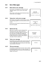
Страница 63: ... following message ap pears and the buzzer sounds Press the R B key to silence the buzzer and return to the normal so nar picture Raise the transducer 8 8 4 Train error message If something is wrong with the train control circuit the fol lowing message appears and the unit stops operating Turn the PWR switch off and contact your service agent at your earliest convenience 8 8 5 Tilt error message I...

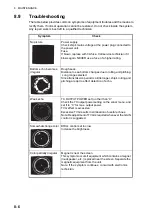
Страница 64: ... and pitching Long range selected Since transmission period is a little longer ship s rolling and pitching are apt to effect detection of echo Weak echo TX OUTPUT POWER set to other than C Check the TX output power setting on the sonar menu and set it to C for max output power TVG effect is excessive Excessive TVG results in elimination of useful echoes Note Readjustment of TVG is required wheneve...

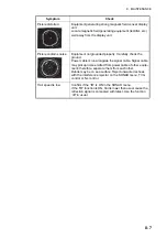
Страница 65: ... is run alongside the signal cable Signal cable may pickup noise emitted from power cable of other equip ment therefore separate them from each other Debris may be on sea surface Reject unwanted echoes with the interference rejector on the SONAR menu TVG control or NL control Trail speed is low Confirm if the IR is ON in the SONAR menu If the IR function is ON trail is lower than usual cause the r...

Страница 66: ...8 MAINTENANCE 8 8 This page is intentionally left blank ...
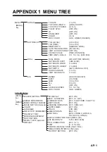
Страница 67: ...RATE 1 to 10 VERT SCAN RATE 1 to 10 RANGE 40 80 160 240 320 SHIFT 0 to 1000 GAIN 0 0 to 10 0 N L 0 to 10 IR OFF ON ADVANCE SPEED 1 1 1 2 1 4 RES COLOR LOG LINEAR 3D DISPLAY OFF ON SHIP S POSITION OFF L L LOP CURRENT DATA OFF FLOW FROM FLOW TO DEPTH DATA OFF ON HEADING INDICATION OFF TRUE AZ NORTH MARK OFF ON TRACK 10R 20R HDG SPD DATA NAV IC NAV DATA GPS LORAN C LORAN A DR DECCA OTHES DATA FORMAT ...

Страница 68: ... 600 0 500 10 0 11 0 1200 0 800 0 600 12 0 12 0 1600 0 1000 0 800 14 0 2 PROCESSOR UNIT 2 1 Picture output 1024 x 764 pixels 16 or 8 colors selectable 2 2 Color hue control LOG linear square 2 3 Display mode Vertical normal expanded Slice combination Sonar combination 2 4 Sensitivity Variable continuity 2 5 Unit indication m ft fa HR 2 6 Horizontal range 12 steps during 30 m to 1600 m 2 7 Vertical...

Страница 69: ...l KP I O TTL for synchronization 4 3 RGB Video signal output XGA VESA DDC for external monitor 5 POWER SUPPLY 5 1 Processor unit 24 VDC 0 5 A max 5 2 Transceiver unit 24 VDC 3 5 A 5 3 Hull unit 24 VDC 3 5 A max 6 5 A while traveling 5 4 Total 24 VDC 13 0 A max 16 0 A while traveling 5 5 Rectifier option RU 3423 RU 1746B 2 100 115 220 240 VAC 1 phase 50 60Hz 6 ENVIRONMENTAL CONDITION 6 1 Ambient te...

Страница 70: ...fan mode 3 1 N Net mouth marker 3 8 How to display the marker 3 8 How to move the marker 3 9 How to resize the marker 3 9 NL control 1 2 Noise 2 9 2 12 3 7 P Power switch 1 3 Presentation mode 1 4 R R B marker 2 6 Range sonar mode 7 3 vertical fan mode 7 3 RANGE control sonar mode 2 3 vertical fan mode 3 2 Remote controller 1 3 S School of fish detecting 2 7 Sea surface reflection 2 7 SECTOR contr...

Страница 71: ... 4 10 5 10 8 and 10 9 IEC 60945 Ed 3 0 1996 clauses 10 2 and 10 3 title and or number and date of issue of the standard s or other normative document s For assessment see EMC Test Report FLI 12 11 118 December 15 2011 prepared by Furuno Labotech International Co Ltd This declaration is issued according to the Directive 2014 30 EU of the European Parliament and of the Council of 26 February 2014 on...

Отзывы: