English
CCD-0005506 Rev: 08-16-22
- 8 -
WARNING
●
DO NOT use matches, candles or other sources of ignition
when checking for gas leaks.
●
Do not smoke while leak testing.
●
Never leak test with an open flame.
Please follow below steps to make leak test for the appliance:
1.
Extinguish all open flames.
2. Turn the gas supply valve and control knobs off.
3. Prepare soap solution mixing of equal parts mild detergent or
liquid soap and water.
4. Spray the soap solution on all gas connections and gas pipes
of the appliance.
5. Turn the gas supply valve on and inspect all gas connections
for bubbles:
−
If no bubbles appeared, there is no gas leak in the
appliance
−
If bubbles appeared, where there are bubbles, where there
is a leak point.
6. If a gas leak is detected, tighten the connection and repeat the
above steps. If the leak is on the gas supply line connection,
replace the gas supply line and repeat above steps.
NOTE:
It is also recommended that you perform a leak test at
least once a year whether the propane gas supply cylinder has
been disconnected or not.
Pressure Check
1.
Extinguish all open flames.
2. Turn the gas supply valve and control knobs off.
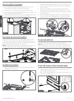
3. Remove the rear vent decoration panel if the rear vent
decoration panel has been installed.
(
NOTE:
See Rear Decorative Panel installation section for
screw locations.)
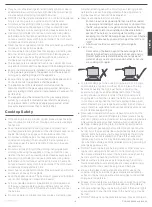
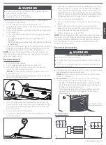
4. Remove the Screw with the sealing gasket from the pressure
test port on the range. (Fig. 5)
Fig. 5
5. Using the rubber tube from the pressure check measuring
device, slide the rubber tube down over the gas pressure test
port. The rubber tube should seal around the pressure test
port on the range.
6. Turn on the LP gas to the appliance.
7. The pressure gauge tester should measure between 10” WC
to 13.8” WC. (Fig. 6)
Fig. 6
8. Write down the pressure reading on the gauge and wait 5 min.
Recheck to see if the reading on the gauge has decreased.
If the gauge reading has decreased, there is a potential leak.
Please check the various gas connections using the bubble
test. If the leak can not be found, please consult with a service
professional and ensure the gas flow to the appliance is off.
9. Turn off the LP gas to the appliance.
10. Remove the rubber tube of the pressure check measuring
device.
11. Replace the screw with the gasket from step 2. Before
replacing the screw, inspect the rubber gasket seal for any
signs of damage. Replace seal if damaged.
12. Tighten the screw to 1.3 Nm to 1.7 Nm.
NOTE:
Ensure the product is gas leak checked after the pressure
check test is completed by also testing the pressure check port
screw. If any leaks are detected around the pressure check port
screw and gasket, a new one can be purchased. Call Furrion
support for a replacement.
Electrical Connection
WARNING
PRODUCT DAMAGE HAZARD
●
Connect to 12V DC service only.
●
Connect only to protected circuit fused for not more than 15
Amps.
●
DO NOT hi-pot range unless electronic ignition system has
been disconnected.
●
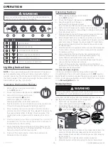
The power supply of this oven is 12V. Connect the components
below separately. (See Wiring Diagram)
NOTE:
Ensure to connect the wires with the correct polarity.
Red is “+” and Black is “-”.
●
12V power for:
Igniter, Oven Light, Cooling fan, Electronic
Timer & Display, 140
o
F (60
o
C) Thermostat Control.
−
Feed the cable through the electrical cord cutout on the
upper rear-right corner of the cabinet, use a 15A fuse at
the power source for protection.
−
The nameplate is located on the cavity frame (near the
door) of the oven, refer to the label for the technical
specifications.
Nameplate Positon
Wiring Diagram
Switch 6
Switch 5
S
wit
ch 4
S
wit
ch 3
S
wit
ch 2
S
wit
ch 1
DV12V+
DV12V-
Lighter
Ignition needle 1
Ignition needle 2
Ignition needle 3
Ignition needle 4
LED 1
Lamp
LED 2 LED 3 LED 4

