


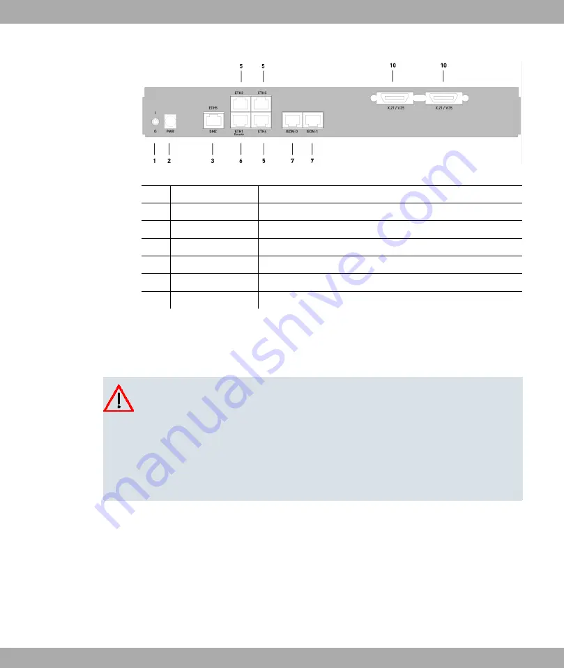
Fig. 11: Back of
bintec R4300
1
I/0
Mains switch
2
PWR
Socket for plug-in power pack
3
DMZ/ETH5
Ethernet interface
5
ETH2 - ETH4
Ethernet interface
6
ETH1 / Console
Ethernet interface with serial interface function
7
ISDN-0 - ISDN-1
ISDN interface
10
X.21 / V.35
X.21 interface
2.4.2 Setting Up and Connecting
All you need for this are the cables and antennas supplied with the equipment.
Caution
The use of the wrong mains adapter may damage your device. Only use the mains ad-
aptor supplied with the equipment.
Incorrect cabling of the ISDN and ETH interfaces may also damage your device. Con-
nect only the ETH interface of the device to the LAN interface of the computer/hub or a
WAN interface if available and the ISDN interface of the device only to the ISDN con-
nection.
Set up and connect in the following sequence:
(1)
Antennas (only R1200w, R1200wu and R3000w): Screw the external standard anten-
nas provided to their RSMA connections Main and AUX and align the antennas.
(2)
Place your device on a solid, level base.
(3)
LAN: For the standard configuration of your device via Ethernet, connect the first
switch port (ETH1) of your device to your LAN using the Ethernet cable supplied. The
device automatically detects whether it is connected to a switch or directly to a PC.
(4)
ADSL (only R3000 and R3000w): Connect the ADSL interface (ADSL) of your device
to the DSL output of the splitter using the DSL cable supplied.
2 Quick Reference
Funkwerk Enterprise Communications GmbH
14
bintec R1xxx/R3xxx/R4xxx


