Appendix B
Components
B-23
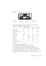
FIGURE B-15
Front of DAT160-compliant Tape Drive Unit (TAPEU)
The TAPEU has the following characteristics.
■
Active replacement or hot replacement of the TAPEU is possible.
■
Active installation of the TAPEU during system operation is possible.
■
The TAPEU complies with DAT72 (SATA interface) or DAT160 (SAS interface).
■
The DAT160-compliant TAPEU has read/write compatibility with DAT72 and DDS4.
■
By changing the switch setting on the TAPEU, it can be used by each domain.
■
The TAPEU has a label bearing the printed component number and manufacture's serial
number.
TABLE B-3
Status Display of LEDs for DAT160-compliant Tape Drive Unit (TAPEU)
Status of DAT160-compliant TAPEU
Status display of LEDs
Clean LED
Tape LED
Drive LED
Ready LED
Power-off status
Off
Off
Off
Off
Drive is available
Off
Off
Off
Lit
Reading, writing, and seeking
operations
Off
Off
Off
Blinking
Cleaning request
Blinking
Off
Off
Off
During cleaning
Lit
Off
Off
Blinking
Self test failed
Off
Blinking
Blinking
Off
Tape failure
Off
Blinking
Off
Off
Drive error
Off
Off
Blinking
Off
Firmware failure
Off
Off
Lit
Lit
(Status display of LEDs repeats
alternately)
Lit
Lit
Off
Off
Drive LED
Tape LED
Clean LED
Ready LED
Содержание SPARC Enterprise M8000
Страница 4: ......
Страница 15: ...Contents xv Index Index 1 ...
Страница 16: ...xvi SPARC Enterprise M8000 M9000 Servers Service Manual October 2012 ...
Страница 22: ......
Страница 27: ...Chapter 1 Safety and Tools 1 5 M9000 Server Front View ...
Страница 29: ...Chapter 1 Safety and Tools 1 7 Power Supply Unit PSU ...
Страница 37: ...Chapter 1 Safety and Tools 1 15 FIGURE 1 10 M9000 Grounding Port Connection Locations Rear View ...
Страница 38: ...1 16 SPARC Enterprise M8000 M9000 Servers Service Manual October 2012 ...
Страница 54: ...2 16 SPARC Enterprise M8000 M9000 Servers Service Manual October 2012 Removing an I O unit IOU ...
Страница 88: ...2 50 SPARC Enterprise M8000 M9000 Servers Service Manual October 2012 ...
Страница 137: ...Chapter 4 FRU Replacement Preparation 4 43 FIGURE 4 12 Magnified View of Part A M8000 Rear View ...
Страница 145: ...Chapter 4 FRU Replacement Preparation 4 51 FIGURE 4 19 Magnified View of Part B M8000 Rear View ...
Страница 148: ......
Страница 154: ...5 6 SPARC Enterprise M8000 M9000 Servers Service Manual October 2012 ...
Страница 180: ...6 26 SPARC Enterprise M8000 M9000 Servers Service Manual October 2012 FIGURE 6 16 CMU Guide Lock Enlarged ...
Страница 204: ...7 12 SPARC Enterprise M8000 M9000 Servers Service Manual October 2012 FIGURE 7 7 Removing the IOU Rear of M8000 1 1 2 3 ...
Страница 205: ...Chapter 7 I O Unit IOU Replacement 7 13 FIGURE 7 8 Removing the IOU Front of M9000 1 1 2 3 ...
Страница 219: ...Chapter 8 FAN Unit Replacement 8 3 FIGURE 8 2 FAN Mounting Locations Rear of the M8000 FAN_B 2 7 7 5 6 4 3 2 ...
Страница 227: ...Chapter 8 FAN Unit Replacement 8 11 FIGURE 8 9 Removing the FAN Unit Rear of M8000 1 2 ...
Страница 251: ...Chapter 10 Operator Panel Replacement 10 3 FIGURE 10 2 OPNL Mounting Location Front of the M9000 Base Cabinet OPNL ...
Страница 256: ...10 8 SPARC Enterprise M8000 M9000 Servers Service Manual October 2012 ...
Страница 272: ...11 16 SPARC Enterprise M8000 M9000 Servers Service Manual October 2012 ...
Страница 312: ...13 30 SPARC Enterprise M8000 M9000 Servers Service Manual October 2012 ...
Страница 340: ...15 14 SPARC Enterprise M8000 M9000 Servers Service Manual October 2012 ...
Страница 358: ...17 10 SPARC Enterprise M8000 M9000 Servers Service Manual October 2012 ...
Страница 361: ...Chapter 18 AC Section Replacement 18 3 FIGURE 18 2 ACS Mounting Location Front of the M9000 Base Cabinet ACS_B ...
Страница 367: ...Chapter 18 AC Section Replacement 18 9 FIGURE 18 5 Removing the AC Section Front of the M9000 1 2 1 ...
Страница 370: ...18 12 SPARC Enterprise M8000 M9000 Servers Service Manual October 2012 ...
Страница 380: ...19 10 SPARC Enterprise M8000 M9000 Servers Service Manual October 2012 ...
Страница 383: ...Chapter 20 Backplane Replacement 20 3 FIGURE 20 2 BP Mounting Locations Front of the M9000 Base Cabinet BP_B ...
Страница 389: ...Chapter 20 Backplane Replacement 20 9 FIGURE 20 4 Preparation for Accessing BP_A Rear of the M8000 ...
Страница 392: ...20 12 SPARC Enterprise M8000 M9000 Servers Service Manual October 2012 FIGURE 20 6 Removing the BP Rear of the M8000 ...
Страница 409: ...Chapter 20 Backplane Replacement 20 29 FIGURE 20 16 Removing the FANBP Rear of the M8000 ...
Страница 410: ...20 30 SPARC Enterprise M8000 M9000 Servers Service Manual October 2012 FIGURE 20 17 Removing the FANBP Front of M8000 ...
Страница 415: ...Chapter 21 Sensor Unit Replacement 21 3 FIGURE 21 2 SNSU Mounting Location Front of the M9000 Base Cabinet SNSU ...
Страница 422: ...21 10 SPARC Enterprise M8000 M9000 Servers Service Manual October 2012 ...
Страница 425: ...Chapter 22 Media Backplane Replacement 22 3 FIGURE 22 2 MEDBP Mounting Location Front of the M9000 Base Cabinet MEDBP ...
Страница 430: ...22 8 SPARC Enterprise M8000 M9000 Servers Service Manual October 2012 FIGURE 22 4 Removing the MEDBP Front of the M8000 ...
Страница 435: ...Chapter 23 Switch Backplane Replacement 23 3 FIGURE 23 2 SWBP Mounting Location Front of the M9000 Base Cabinet SWBP ...
Страница 439: ...Chapter 23 Switch Backplane Replacement 23 7 FIGURE 23 4 Removing the SWBP Rear of the M8000 ...
Страница 442: ...23 10 SPARC Enterprise M8000 M9000 Servers Service Manual October 2012 ...
Страница 460: ...24 18 SPARC Enterprise M8000 M9000 Servers Service Manual October 2012 ...
Страница 484: ...25 24 SPARC Enterprise M8000 M9000 Servers Service Manual October 2012 ...
Страница 494: ...A 10 SPARC Enterprise M8000 M9000 Servers Service Manual October 2012 ...
Страница 537: ...Appendix B Components B 43 FIGURE B 38 FAN Backplane FANBP_B FIGURE B 39 FAN Backplane FANBP_C ...
Страница 544: ...C 4 SPARC Enterprise M8000 M9000 Servers Service Manual October 2012 ...
Страница 552: ...D 8 SPARC Enterprise M8000 M9000 Servers Service Manual October 2012 ...


