background image

RX1330 M3

Upgrade and Maintenance Manual

275

System board and components

14.2.1.1 Preliminary steps

Ê

"Locating the defective server" on page 50

Ê

"Shutting down the server" on page 53

Ê

"Disconnecting the power cord" on page 54

Ê

"Getting access to the component" on page 55

Ê

If there is an expansion card attached to slot 3, remove the riser module 3 
as described in section 

"Removing the riser card" on page 204

.

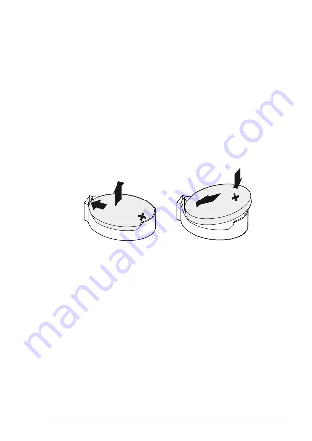
14.2.1.2 Replacing the defective CMOS battery

Figure 188: Replacing the CMOS battery

Ê

Press the locking spring into direction of the arrow (1), so that the CMOS 
battery jumps out of its socket.

Ê

Remove the CMOS battery (2).

V

CAUTION!

Sharp tools such as screw drivers might damage system board 
components in case of slipping.

If the CMOS battery cannot be ejected without the help of a tool, it is 
recommended to use a tooth pick. 

Ê

Insert a new CMOS battery of the same type into the socket (3) and (4).

1

2

3

4

Содержание PRIMERGY RX1330 M3

Страница 1: ...Upgrade and Maintenance Manual English FUJITSU Server PRIMERGY RX1330 M3 Upgrade and Maintenance Manual April 2017 ...

Страница 2: ...tas de Copyright and Trademarks Copyright 2017 FUJITSU LIMITED All rights reserved Delivery subject to availability right of technical modifications reserved All hardware and software names used are trademarks of their respective manufacturers The contents of this manual may be revised without prior notice Fujitsu assumes no liability for damages to third party copyrights or other rights arising f...

Страница 3: ...of these components beyond their operating life may result in electrolyte leakage or depletion potentially causing emission of foul odor or smoke As a guideline in a normal office environment 25 C operating life is not expected to be reached within the maintenance support period 5 years However operating life may be reached more quickly if for example the product is used in a hot environment The c...

Страница 4: ...Voltage Dip Immunity of Personal Computer issued by JEITA the Japan Electronics and Information Technology Industries Association Technology controlled by the Foreign Exchange and Foreign Trade Control Law of Japan Documents produced by Fujitsu may contain technology controlled by the Foreign Exchange and Foreign Trade Control Law of Japan Documents which contain such technology should not be expo...

Страница 5: ...ual Only for Japan Shielded LAN cables should be used in this product Only for Japan I Although described in this manual some sections do not apply for Japan These options and routines include CSS Customer Self Service USB Flash Module UFM ...

Страница 6: ...Upgrade and Maintenance Manual RX1330 M3 Version history Issue number Reason for update 1 0 April 2017 Initial release ...

Страница 7: ...at hand 32 3 Important information 35 3 1 Safety instructions 35 3 2 ENERGY STAR 44 3 3 CE conformity 44 3 4 FCC Class A Compliance Statement 45 3 5 Environmental protection 46 4 Basic hardware procedures 49 4 1 Using diagnostics information 49 4 1 1 Locating the defective server 50 4 1 2 Determining the error class 50 4 1 2 1 Global Error indicator 50 4 1 2 2 Customer Self Service CSS indicator 5...

Страница 8: ...tionality 71 5 1 2 Disabling SVOM boot watchdog functionality 72 5 1 2 1 Viewing boot watchdog settings 72 5 1 2 2 Configuring boot watchdog settings 73 5 1 3 Removing backup and optical disk media 74 5 1 4 Verifying and configuring the backup software solution 75 5 1 5 Note on server maintenance in a Multipath I O environment 75 5 1 6 Switching on the ID indicator 78 5 2 Completing the maintenanc...

Страница 9: ...16 Looking up changed MAC WWN addresses 97 5 2 16 1 Looking up MAC addresses 97 5 2 16 2 Looking up WWN addresses 97 5 2 17 Using the Chassis ID Prom Tool 98 5 2 18 Configuring LAN teaming 99 5 2 18 1 After replacing upgrading LAN controllers 99 5 2 18 2 After replacing the system board 100 5 2 19 Switching off the ID indicator 100 5 2 20 Performing a fan test 101 6 Power supply unit PSU 103 6 1 B...

Страница 10: ...ing the new power distribution board 119 6 3 4 4 Concluding steps 120 6 4 Fujitsu battery unit FJBU 121 6 4 1 Installing the FJBU 121 6 4 1 1 Preliminary steps 121 6 4 1 2 Removing the dummy cover 121 6 4 1 3 Installing an FJBU 122 6 4 1 4 Concluding steps 122 6 4 2 Removing the FJBU 122 6 4 2 1 Preliminary steps 123 6 4 2 2 Removing an FJBU 123 6 4 2 3 Installing the dummy cover 124 6 4 3 Replaci...

Страница 11: ... Concluding steps 146 7 2 6 Removing 2 5 inch HDD SSD modules 147 7 2 6 1 Preliminary steps 147 7 2 6 2 Removing a 2 5 inch HDD SSD module 148 7 2 6 3 Installing a 2 5 inch HDD SSD dummy module 148 7 2 6 4 Concluding steps 148 7 2 7 Replacing a 2 5 inch HDD SSD module 149 7 2 7 1 Preliminary steps 150 7 2 7 2 Removing the defective 2 5 inch HDD SSD module 150 7 2 7 3 Installing the new 2 5 inch HD...

Страница 12: ... 168 7 3 2 Installing 3 5 inch HDD modules 169 7 3 2 1 Preliminary steps 169 7 3 2 2 Removing a 3 5 inch HDD dummy module 169 7 3 2 3 Installing a 3 5 inch HDD module 170 7 3 2 4 Concluding steps 170 7 3 3 Removing 3 5 inch HDD modules 171 7 3 3 1 Preliminary steps 171 7 3 3 2 Removing a 3 5 inch HDD module 172 7 3 3 3 Installing a 3 5 inch dummy module 172 7 3 3 4 Concluding steps 172 7 3 4 Repla...

Страница 13: ... 3 Handling SFP transceiver modules 191 9 3 1 Installing SFP transceiver modules 191 9 3 2 Removing an SFP transceiver module 194 9 4 Expansion cards and riser cards 197 9 4 1 Installing an expansion card 197 9 4 1 1 Preliminary steps 197 9 4 1 2 Removing the slot cover 197 9 4 1 3 Installing the expansion card 198 9 4 1 4 Concluding steps 198 9 4 2 Removing an expansion card 199 9 4 2 1 Prelimina...

Страница 14: ...U 214 9 5 1 1 Preliminary steps 214 9 5 1 2 Preparing the FBU 214 9 5 1 3 Installing the FBU 216 9 5 1 4 Concluding steps 217 9 5 2 Removing an FBU 218 9 5 2 1 Preliminary steps 218 9 5 2 2 Removing the FBU with the holder 218 9 5 2 3 Disconnecting the FBU cable from the FBU 219 9 5 2 4 Removing the FBU from the holder 219 9 5 2 5 Concluding steps 220 9 5 3 Replacing an FBU 220 9 5 3 1 Preliminary...

Страница 15: ... 2 Upgrading or replacing the CPU 232 11 2 1 Preliminary steps 232 11 2 2 Removing the heat sink 233 11 2 3 Removing the CPU 234 11 2 4 Installing the CPU 235 11 2 5 Applying the thermal paste 238 11 2 6 Installing the heat sink 240 11 2 7 Concluding steps 241 11 3 Replacing the heat sink 242 11 3 1 Preliminary steps 242 11 3 2 Removing the defective heat sink 242 11 3 3 Installing the new heat si...

Страница 16: ... 258 13 2 1 2 Removing the front panel module 259 13 2 1 3 Installing the front panel module 261 13 2 1 4 Concluding steps 263 13 3 Front VGA board 263 13 3 1 Installing the front VGA board 263 13 3 1 1 Preliminary steps 263 13 3 1 2 Removing the dummy cover 264 13 3 1 3 Installing the front VGA board 264 13 3 1 4 Concluding steps 265 13 3 2 Removing the front VGA board 265 13 3 2 1 Preliminary st...

Страница 17: ...FM 276 14 3 1 Installing the UFM 276 14 3 1 1 Preliminary steps 276 14 3 1 2 Installing the UFM 277 14 3 1 3 Concluding steps 278 14 3 1 4 Software configuration 278 14 3 2 Removing the UFM 279 14 3 2 1 Preliminary steps 279 14 3 2 2 Removing the UFM 280 14 3 2 3 Concluding steps 281 14 3 3 Replacing the UFM 282 14 3 3 1 Preliminary steps 282 14 3 3 2 Removing the defective UFM 282 14 3 3 3 Instal...

Страница 18: ...297 14 5 3 2 Replacing the SATA DOM 297 14 5 3 3 Concluding steps 297 14 6 iRMC microSD card 298 14 6 1 Installing the iRMC microSD card 298 14 6 1 1 Preliminary steps 298 14 6 1 2 Installing the iRMC microSD card 298 14 6 1 3 Concluding steps 299 14 6 2 Removing the iRMC microSD card 299 14 6 2 1 Preliminary steps 299 14 6 2 2 Removing the iRMC microSD card 300 14 6 2 3 Concluding steps 300 14 6 ...

Страница 19: ...n the system board 324 16 2 1 1 Onboard connectors 324 16 2 1 2 Onboard indicators and controls 326 16 2 2 Server front 328 16 2 2 1 Indicators on the front panel 328 16 2 2 2 Indicators on the accessible drives components 332 16 2 3 Server rear 334 16 2 3 1 Connectors on the I O panel 334 16 2 3 2 Indicators on the I O panel 335 16 2 3 3 Indicator on hot plug PSUs slide in unit 338 16 2 3 4 Indic...

Страница 20: ...Upgrade and Maintenance Manual RX1330 M3 Contents ...

Страница 21: ...ing defective hardware components This manual focuses on on site maintenance tasks It is recommended to prepare each service assignment following remote diagnostics procedures as described in the ServerView Suite Local Service Concept LSC manual see section Documents you need at hand on page 32 V CAUTION The document at hand comprises procedures of a wide range of complexity Check the profile of q...

Страница 22: ...at are being emphasized Ê describes activities that must be performed in the order shown Abc indicates keys on the keyboard V CAUTION Pay particular attention to texts marked with this symbol Failure to observe this warning may endanger your life destroy the system or lead to the loss of data I indicates additional information notes and tips indicates the procedure category in terms of complexity ...

Страница 23: ... Tools you need at hand on page 29 Advanced Thermal Design The Advanced Thermal Design option allows you to operate the system with a wider temperature range of 5 C to 40 C depending on your system and configuration V CAUTION In a system that is configured with Advanced Thermal Design only certain components which support the respectively increased higher operating temperature range may be install...

Страница 24: ...re available online at http manuals ts fujitsu com illustrated_spares not valid for Japan Replacing a defective component The Global Error indicator on the front of the server reports defective hardware components that need to be replaced For further information on the controls and indicators of your server refer to the operating manual of your server and section Connectors and indicators on page ...

Страница 25: ... Customer Replaceable Units CRU Customer Replaceable Units are intended for customer self service and may be installed or replaced as hot plug components during operation I Components that the customer is entitled to replace may differ according to the service form in his country Hot plug components increase system availability and guarantee a high degree of data integrity and fail safe performanc...

Страница 26: ...or messages and diagnostic indicators on the front panel and system board will report defective Upgrade and Repair Units as customer replaceable CSS components Upgrade and repair procedures involve shutting down and opening the server V CAUTION The device may be seriously damaged or cause damage if it is opened without authorization or if repairs are attempted by unauthorized and untrained personn...

Страница 27: ...able Units must be performed exclusively by Fujitsu service personnel or technicians trained by Fujitsu Please note that unauthorized interference with the system will void the warranty and exempt the manufacturer from all liability Components that are handled as Field Replaceable Units CPU replacement SAS SATA backplanes SAS expander board Power distribution board Front panel module System board ...

Страница 28: ...re described in section Starting the maintenance task on page 71 Rack removal disassembly yes making the server available removing the server from the rack if applicable Transport no Transporting the server to the service table where required depends on local customer conditions Maintenance procedures yes maintenance procedures including preliminary and concluding software tasks Transport no Retur...

Страница 29: ... driver bit insert Torque Screw Usage Type Phillips PH2 No 2 0 6 Nm Slot bracket to chassis system board M3 x 4 5mm silver C26192 Y10 C67 C26192 Y10 C207 Phillips PH2 No 2 0 6 Nm Slot bracket to expansion card M3 x 3 5 mm silver C26192 Y10 C151 Phillips PH2 No 2 0 6 Nm 3 5 inch HDD UNC 6 32 x 3 5 mm silver A3C40151505 Phillips PH1 No 1 0 4 Nm Front VGA 2 5 inch HDD M3 x 3 5 mm silver C26192 Y10 C1...

Страница 30: ...nylon screw M3 x 4 mm white A3C40109082 Phillips PH1 No 1 0 4 Nm TFM M2 5 x 4 mm silver A3C40137316 Hexagon bolt 0 6 Nm Front VGA connector UNC 4 40x7 8 mm silver V26827 B408 V989 Phillips PH1 No 1 0 4 Nm Front panel on QRL M2 5 x 8 mm silver C26192 Y10 C174 Screw driver bit insert Torque Screw Usage Type Table 2 List of used screws not valid for Japan ...

Страница 31: ...Slot bracket to expansion card M3 x 5 mm silver F6 SW2N3 06121 Phillips PH2 No 2 0 6 Nm 3 5 inch HDD UNC 6 32 x 3 5 mm silver A3C40151505 Phillips PH1 No 1 0 4 Nm Front VGA 2 5 inch HDD M3 x 3 5 mm silver CA32432 0023 Special bit insert 0 6 Nm TPM screw REM 3 x 15 mm black C26192 Y10 C176 Phillips PH1 No 1 0 09 Nm ODD latch M2 x 3mm black F6 SW4N2 03121 Phillips PH1 No 1 0 06 Nm UFM nylon screw M3...

Страница 32: ...a save place for future reference Unless stated otherwise all manuals are available online at http manuals ts fujitsu com under x86 Servers For Japan please use the following address http www fujitsu com jp products computing servers primergy manual Phillips PH1 No 1 0 4 Nm TFM M2 5 x 4 mm silver A3C40137316 Hexagon bolt 0 6 Nm Front VGA connector UNC 4 40x7 8 mm silver V226827 B265 V5 Phillips PH...

Страница 33: ... BIOS options and parameters available online System board label Label inside the top cover outlining connectors indicators and jumper Software documentation ServerView Suite Local Service Concept LSC user guide ServerView Operations Manager Server Management user guide iRMC S4 Integrated Remote Management Controller user guide ServerView embedded Lifecycle Management eLCM user guide Illustrated S...

Страница 34: ...dditional documentation RAID documentation available online at http manuals ts fujitsu com under x86Servers Expansion Cards Storage Adapters For Japan please use the following address http www fujitsu com jp products computing s ervers primergy manual Third party documentation Operating system documentation online help Peripherals documentation Document Description Table 4 Documentation you need a...

Страница 35: ...tact your sales outlet or our customer service team The actions described in this manual shall be performed by technical specialists A technical specialist is a person who is trained to install the server including hardware and software Repairs to the server that do not relate to CSS failures shall be performed by service personnel Please note that unauthorized interference with the server will vo...

Страница 36: ...e to 40 C or 45 C If the server is integrated into an installation that draws power from an industrial power supply network with an IEC309 connector the power supply s fuse protection must comply with the requirements for non industrial power supply networks for type A connectors The server automatically adjusts itself to a mains voltage see the type label of your server Ensure that the local main...

Страница 37: ...t data transmission lines during a storm risk of lightning hazard Make sure that no objects e g jewelry paperclips etc or liquids can get inside the server risk of electric shock short circuit In emergencies e g damaged casing controls or cables penetration of liquids or foreign bodies contact the server administrator or your customer service team Only disconnect the server from the mains power su...

Страница 38: ...nd will void the warranty and exempt the manufacturer from all liability The circuit boards and soldered parts of internal options are exposed and can be damaged by static electricity To ensure reliable protection you must wear an earthing band on your wrist when working with this type of module and connect it to an unpainted conducting metal part of the server Do not touch the circuitry on boards...

Страница 39: ... must be followed V CAUTION Only use CDs DVDs BDs that are in perfect condition in order to prevent data loss equipment damage and injury Check each CD DVD BD for damage cracks breakages etc before inserting it in the drive Note that any additional labels applied may change the mechanical properties of a CD DVD BD and cause imbalance and vibrations Damaged and imbalanced CDs DVDs BDs can break at ...

Страница 40: ...ners water record sprays antistatic agents or silicone impregnated cloth Be careful not to damage the CD DVD BD surface Keep the CDs DVDs BDs away from heat sources Do not bend or place heavy objects on CDs DVDs BDs Do not write with ballpoint pen or pencil on the label printed side Do not attach stickers or similar to the label side Doing so may cause rotational eccentricity and abnormal vibratio...

Страница 41: ...25 1 laser class 1 V CAUTION The optical disk drive contains a light emitting diode LED which under certain circumstances produces a laser beam stronger than laser class 1 Looking directly at this beam is dangerous Never remove parts of the optical disk drive casing Modules with Electrostatic Sensitive Devices ESD modules Modules with electrostatic sensitive devices are identified by the following...

Страница 42: ...ic charge I For a detailed description of how to handle ESD modules see the relevant European or international standards EN 61340 5 1 ANSI ESD S20 20 Transporting the server V CAUTION Only transport the server in its original packaging or in packaging that protects it from impacts and jolts In Japan and APAC transporting the server in its original packaging does not apply Do not unpack the server ...

Страница 43: ... See the safety information of the rack and the warning label If the server rack is intended for permanent connection to the mains only an authorized specialist electrician is allowed to work Please follow the regulation of each country If the server is integrated into an installation that draws power from an industrial power supply network with an IEC309 type connector the power supply s fuse pro...

Страница 44: ... reading out measurement values including those relating to current energy consumption and air temperatures Either the Performance Monitor or the Task Manager can be used to read out CPU utilization levels The system complies with the requirements of European Regulations Find the CE declaration on certificate portal https sp ts fujitsu com sites certificates default aspx To open the CE declaration...

Страница 45: ...nterference will not occur in a particular installation If this equipment does cause harmful interference to radio or television reception which can be determined by turning the equipment off and on the user is encouraged to try to correct the interference by one or more of the following measures Reorient or relocate the receiving antenna Increase the separation between equipment and the receiver ...

Страница 46: ...ly switched on should be switched off until they are needed as well as during long breaks and after completion of work Packaging information This packaging information does not apply in Japan and APAC Do not throw away the packaging You may need it later for transporting the server If possible the equipment should only be transported in its original packaging Information on handling consumables Pl...

Страница 47: ... consumables within Europe can also be found in the Returning used devices manual via your local Fujitsu branch or at http ts fujitsu com recycling The device must not be disposed of with domestic waste This device is labeled in compliance with European directive 2012 19 EU on waste electrical and electronic equipment WEEE This directive sets the framework for returning and recycling used equipmen...

Страница 48: ...48 Upgrade and Maintenance Manual RX1330 M3 Important information ...

Страница 49: ...l Service Concept LSC manual I In Japan remote diagnostics procedures are not used Please contact your local Fujitsu customer service partner for details on the service concept and on how to order expansion kits or spare parts Use the Fujitsu Illustrated Spares Catalog to identify the required spare part and obtain technical data and order information Illustrated Spares catalogs are available onli...

Страница 50: ... off the ID indicator after the maintenance task has been concluded successfully 4 1 2 Determining the error class The Local Service Concept LSC allows you to identify defective server components Failure events are assigned to one of two error classes Global Error events that need to be resolved by maintenance personnel Customer Self Service CSS error events that may be resolved by operating perso...

Страница 51: ... based servers with ServerView agents installed I For further information please refer to the ServerView System Monitor user guide 4 1 3 Locating the defective component After determining the error class by the CSS or Global Error indicators see section Determining the error class on page 50 local diagnostic indicators on the system board HDD modules and PSUs only slide in units allow you to ident...

Страница 52: ...ents see section Onboard indicators and controls on page 326 Component LEDs Ê Check the component LEDs on the system board and the server rear see section Connectors and indicators on page 324 I In addition to local diagnostic indicators CSS or Global Error LEDs indicate if the defective component is a customer replaceable unit or if a service technician needs to be dispatched to replace the part ...

Страница 53: ...stem administrator that the server will be shut down and put offline Ê Terminate all applications Ê Perform the required procedures described in the preliminary steps of each upgrade or maintenance task Ê Shut down the server I If the system is running an ACPI compliant operating system pressing the On Off button will perform a graceful shutdown Ê Switch on the ID indicator on the front and rear c...

Страница 54: ... PSU Ê Pull out on the locking lever on the cable tie 1 and loosen the loop 2 Ê Disconnect the power cord from the PSU and remove it from the cable tie Redundant power supply Figure 3 Unlocking the cable clamp of a PSU Ê Press the cable clamp down until it disengages 1 Ê Open the cable clamp 2 Ê Disconnect the power cord from the PSU and remove it from cable clamp 햲 햳 0 ...

Страница 55: ...all peripheral devices and any other connected devices Also unplug all power cords from the outlet Failure to do so can cause electric shock The top cover must be replaced as soon as possible for purposes of cooling to comply with EMC regulations regulations regarding electromagnetic compatibility and to prevent fires For further safety information please refer to chapter Important information on ...

Страница 56: ...es when sliding out the server or pushing it back Failure to do so may cause injury For further safety information please refer to chapter Important information on page 35 Ê Remove all remaining external cables from the rear connector panel and expansion cards Figure 4 Extending the server out of the rack Ê Fold down the two quick release levers 1 Ê Pull the server out of the rack until it locks i...

Страница 57: ...the rack cabinet For Japan please refer to 安全上のご注意 Additionally a lifter is required in the following cases The server weighs more than 50 kg The server weighs more than 21 kg and is installed above the height of 25 U When using a lifter this removal procedure needs to be carried out by maintenance personnel For configurations below 32 kg At least two people are needed to lift the server out of th...

Страница 58: ...ntenance Manual RX1330 M3 Basic hardware procedures Figure 5 Removing the server from the rack Ê Release the locking bars on both rack rails 1 Ê Lift the server out of the rack rails 2 and place it on an even surface 햲 햳 ...

Страница 59: ...nual 59 Basic hardware procedures 4 4 3 Removing the top cover Figure 6 Removing the top cover Ê Push green touch points inside 1 Ê Push the top cover as far as it will go in the direction of the arrow 2 Ê Lift off the top cover upward 3 ...

Страница 60: ...soon as possible for purposes of cooling to comply with EMC regulations regulations regarding electromagnetic compatibility and to prevent fires For further safety information please refer to chapter Important information on page 35 4 5 1 Installing the top cover Figure 7 Attaching the top cover Ê Place the top cover on the server 1 Ê Push the top cover as far as it will go in the direction of the...

Страница 61: ...re than 50 kg The server weighs more than 21 kg and is to be installed above the height of 25 U When using a lifter this installation procedure needs to be carried out by maintenance personnel For configurations below 32 kg At least two people are needed to lift the server into the rack cabinet For configurations below 55 kg At least three people are needed to lift the server into the rack cabinet...

Страница 62: ... I The rack rails must click into place so that they can no longer be moved Ê At a slight angle lower the server onto the rear mounting point on the rack rails 2 Ê Fold down the server while pressing the rail to the server side 3 Ensure that all six rack mounting bolts are properly seated in the mounting points on the rack rails and that the locking bars engage 4 햲 햲 햴 햵 햳 햳 ...

Страница 63: ...ase the locking mechanism of both rails 1 Ê Push the server as far as it will go into the rack 2 until the quick release levers engage 3 V CAUTION Be careful with your fingers You can pinch them when the quick release levers change to the release position Ê Reconnect all cables except the power cord to the server rear 햲 햴 햲 햲 햳 햳 햴 햴 햴 햴 햴 햴 햴 햴 햴 햴 햴 햴 햴 햴 ...

Страница 64: ...orresponds to the local mains voltage Standard power supply Ê If applicable connect the mains plug to a grounded mains outlet in the in house power supply network Ê Connect the power cord to the PSU Figure 10 Example Locking the cable tie of a standard PSU Ê Thread the cable tie through the eye 1 Ê Pull the cable tie tight to secure the power cord 2 The insulated connector cannot now be disconnect...

Страница 65: ...power source should fail the server will still continue to run Ê Connect the power cords to the PSUs Ê Ensure that the status indicator on the PSU is lit green see section Indicator on hot plug PSUs slide in unit on page 338 Figure 11 Example Locking the cable clamp of a PSU Ê Pull the cable clamp up 1 Ê Thread the power cord through the cable clamp 2 Ê Press the cable clamp down until it engages ...

Страница 66: ...ooling requirements the server must not run while the top cover is removed For further safety information please refer to chapter Important information on page 35 Ê Press the On Off button to start up the server Ê Ensure that the power on indicator above the On Off button is lit green Ê Perform the required procedures described in the concluding steps of each upgrade or maintenance task 4 8 Handli...

Страница 67: ...c hardware procedures Figure 13 Removing the riser module 2 Figure 14 Removing the riser module 3 Figure 15 Removing the full height riser module Ê If necessary disconnect cables from the other components Ê Carefully pull out the riser module upward ...

Страница 68: ... and Maintenance Manual RX1330 M3 Basic hardware procedures 4 8 2 Installing a riser module Figure 16 Installing the riser module 1 Figure 17 Installing the riser module 2 Figure 18 Installing the riser module 3 ...

Страница 69: ...ll height riser module Ê Insert the riser card into the system board slot and press down the green touch points see circles V CAUTION Valid for the full height riser module Make sure that the EMC springs make contact correctly see close ups Ê If necessary connect the cables to the other components ...

Страница 70: ...70 Upgrade and Maintenance Manual RX1330 M3 Basic hardware procedures ...

Страница 71: ...tion without decrypting the drive Windows is installed on Suspend BitLocker before modifying the server s hardware configuration or startup files Resume BitLocker again after the maintenance procedure is complete V CAUTION With BitLocker features enabled modifying the system configuration hardware or firmware settings may render the system inaccessible The system may enter Recovery Mode and requir...

Страница 72: ... Click Yes to confirm that your data will not be protected while BitLocker is suspended I In order to determine which features are accessible through the BitLocker setup wizard it may be necessary to modify the BitLocker Group Policy settings For further information on how to suspend BitLocker drive encryption please refer to the Microsoft TechNet library at http technet microsoft com library cc73...

Страница 73: ...e Viewing boot watchdog settings in ServerView Operations Manager Ê In ServerView Operations Manager Single System View select Maintenance from the Information Operation menu Ê Under ASR R select the Watchdog tab to obtain detailed information about the current watchdog status time out intervals and actions that are triggered if watchdog time outs are exceeded I For more detailed information refer...

Страница 74: ...anagement Controller user guide 5 1 3 Removing backup and optical disk media Ê Ask the system administrator to eject all remaining backup or optical media from the backup or optical disk drive before removing it from the server Ê If the backup media cannot be ejected by conventional means and it is mandatory that the cartridge be removed prior to returning the drive for repair or disposing it a ma...

Страница 75: ...perform an offline BIOS firmware update using the ServerView Update DVD or collect diagnostic data using PrimeCollect in a Multipath I O environment there is a risk of damaging the system configuration which may leave the system unable to boot I This is a known restriction of Windows PE with Multipath drivers Using Update Manager Express Ê If performing an offline BIOS firmware update first of all...

Страница 76: ...from the prepared Update DVD or USB stick DVD Ê Switch on the server Ê Right after switching on the server insert the Update DVD into the DVD drive and close the tray USB Ê Connect the USB stick to the server Ê Switch on the server If the server does not boot from DVD or USB stick proceed as follows Ê Reboot the server e g by pressing the reset button on the front or switching the server off and t...

Страница 77: ...er e g by pressing the reset button on the front or switching the server off and then on again after a few seconds Ê Once the server has been started press F12 to enter the boot menu Ê Use the Ê and Ë cursor keys to select your DVD drive as boot device and press ENTER The server will now boot from the ServerView Suite DVD Ê After the boot process is complete select your preferred GUI language Ê In...

Страница 78: ...Local Service Concept LSC and Integrated Remote Management Controller user guides Using the ID button on the front panel Ê Press the ID button on the front panel to switch on the system identification LEDs I For further information refer to section Server front on page 328 Using the iRMC web frontend Ê Enter the ServerView iRMC web frontend Ê Under System Overview click Identify LED On to switch o...

Страница 79: ...ty for any damage done to the server or for the loss of any data resulting from BIOS updates 5 2 1 1 Updating or recovering the system board BIOS BIOS flash procedure Ê Perform the BIOS flash procedure as described in the BIOS Setup Utility reference manual of your server BIOS recovery procedure Ê Perform the BIOS recovery procedure as described in the BIOS Setup Utility reference manual of your s...

Страница 80: ...of the flash process remove the USB stick and restart the server iRMC recovery procedure Ê Prepare a USB stick including the bootable iRMC firmware update image Ê Ensure that the server has been shut down and disconnected from the mains as described in section Disconnecting the power cord on page 54 Ê Connect the USB stick containing the iRMC firmware to a USB port Ê Connect the server to the main...

Страница 81: ...ID EPROM After replacing the system board the backup data is restored from the Chassis ID board to the new system board In order to verify whether the backup or restore process has been successful check the System Event Log SEL using the ServerView Operations Manager see also section Viewing and clearing the System Event Log SEL on page 92 After replacing the system board Ê Check the SEL log files...

Страница 82: ...tely Using the ServerView Update Manager For a detailed description on how to update the expansion card firmware using the ServerView Update Manager or Update Manager Express UME please refer to the following manuals ServerView Update Manager ServerView Update Management user guide ServerView Update Manager Express Local System Update for PRIMERGY Servers user guide Using the flash tool The latest...

Страница 83: ...ller that may require frequent setup or temporarily for one time configuration When permanently enabling a controllers s Option ROM keep in mind that only two Option ROMs can be activated in the system board BIOS at a time Ê Enter the BIOS Ê From the Advanced menu select Option ROM Configuration Ê Identify the desired PCI slot and set its Launch Slot OpROM setting to Enabled Ê Save your changes an...

Страница 84: ...lable from the Fujitsu web pages Re enabling backup drives If a backup drive has been disabled or deleted from the backup software drive list as described in section Verifying and configuring the backup software solution on page 75 it has to be re enabled to complete the maintenance task Ê Re enable backup drives and revise backup software settings and cronjobs I Further information on suitable ba...

Страница 85: ...alue Please take into account that the specified number of boot attempts can only be determined after this period of time If the customer knows about the original boot retry values proceed as follows to reset or configure the boot retry counter Resetting the boot retry counter in the BIOS Ê Enter the BIOS Ê Select the Server Mgmt menu Ê Under Boot Retry Counter press the or keys to specify the max...

Страница 86: ...ect I For detailed information on iRMC settings refer to the Integrated Remote Management Controller user guide 5 2 7 Resetting the error status after replacing memory modules or CPUs 5 2 7 1 Memory modules ServerView Operations Manager may report a defective memory module in case of a memory error I Important note After replacing a defective memory module please check if the error counter has bee...

Страница 87: ...l status issues have been resolved in ServerView Operations Manager Using the command line interface Linux VMware only The memory error counter can be reset using the meclear utility which is part of the ServerView agents for Linux I meclear Memory Module Error Counter Reset Utility allows to reset the error count collected for a memory module for example after it has been replaced For further det...

Страница 88: ...rt Apps Fujitsu Maintenance Tools Ê Choose the CPU status tab Ê Select the CPU which shows the pre failure status Ê Click on Reset Status Ê Ensure that all pre fail fail status issues have been resolved in ServerView Operations Manager Using the command line Linux only Proceed as follows to reset the error counter of a specific CPU Ê Log in as root Ê Enter the command below followed by ENTER For r...

Страница 89: ...all pre fail fail status issues have been resolved in ServerView Operations Manager 5 2 8 Enabling SVOM boot watchdog functionality If ServerView Operations Manager boot watchdog functionality has been disabled for firmware upgrade purposes see section 5 1 2 on page 72 it has to be re enabled to complete the maintenance task Timer settings can be configured in the BIOS or using the ServerView iRMC...

Страница 90: ...ystem BIOS When a CPU an expansion card or a memory module fails the defective component will be set to Disabled or Failed in the system BIOS The server will then reboot with only the intact hardware components remaining in the system configuration After replacing the defective component it needs to be re enabled in the system board BIOS Ê Enter the BIOS Ê Select the Advanced menu Ê Select the sta...

Страница 91: ...dvanced menu Ê Under Memory Status verify that none of the memory modules are marked as Failed Ê Save your changes if applicable and exit the BIOS I For detailed information on how to access the BIOS and modify settings refer to the corresponding BIOS Setup Utility reference manual 5 2 11 Verifying the system time settings I This task only applies to Linux and VMware environments After the system ...

Страница 92: ...SEL 5 2 12 1 Viewing the SEL You can view the System Event Log SEL using the ServerView Operations Manager or the ServerView iRMC web frontend Viewing the SEL in ServerView Operations Manager Ê In ServerView Operations Manager Single System View select Maintenance from the Information Operation menu Ê Under Maintenance select System Event Log Ê Select the message type s you want to display Critica...

Страница 93: ...e Internal Event Log submenu Ê Under Internal Event Log Content the SEL is being displayed In order to filter the list select the check boxes next to the desired event types and press Apply for the changes to take effect I For detailed information on iRMC settings refer to the Integrated Remote Management Controller user guide 5 2 12 2 Clearing the SEL You can clear the System Event Log SEL using ...

Страница 94: ... definition file on the client system Use the following information as reference Ask the system administrator to change the definition file Ê After replacing a network controller or the system board switch on and boot the server as described in section Switching on the server on page 66 kudzu the hardware configuration tool for Red Hat Linux will launch at boot and detect the new and or changed ha...

Страница 95: ...ecovery key when rebooting the server after the maintenance task However if BitLocker functionality has not been suspended Windows will enter recovery mode and ask you to input recovery key for further booting Ê In this case ask the system administrator to enter the recovery key in order to boot the operating system Ê Ask the system administrator to enable the previously suspended BitLocker protec...

Страница 96: ...will be performed completely unattended as a background process Ê Ensure that the RAID array rebuild has started normally Wait until the progress bar has reached at least one percent Ê Inform the customer about the remaining rebuild time based on the displayed duration estimate Figure 20 Progress bar RAID array rebuild V CAUTION The system is now operational however data redundancy will not be ava...

Страница 97: ...anaged PRIMERGY server including its MAC address I This information is only available with the iRMC S4 or above Only network controllers supporting the Command Line Protocol CLP will be displayed Ê Inform the customer about the changed MAC address 5 2 16 2 Looking up WWN addresses Emulex FC FCoE adapters Ê Enable the network controller s Option ROM in the system board BIOS as described in section ...

Страница 98: ...the Chassis ID Prom Tool The Chassis ID EPROM located on a dedicated Chassis ID board or on your server s front panel board contains system information like server name and model housing type serial number and manufacturing data In order to integrate your system into the ServerView management environment and to enable server installation using the ServerView Installation Manager system data needs ...

Страница 99: ...rverView Operations Manager to obtain detailed information on existing LAN teams Ê In ServerView Operations Manager Single System View select System Status from the Information Operation menu Ê Under Network Interfaces select LAN Teaming Ê The Network Interfaces Summary overview shows all configured LAN teams and their components Choose a LAN team to display further details LAN Team Properties Pro...

Страница 100: ...nd or ServerView Operations Manager to switch off the ID indicator after the maintenance task has been concluded successfully I For further information refer to section Locating the defective server on page 50 or to the ServerView Suite Local Service Concept LSC and Integrated Remote Management Controller user guides Using the ID button on the front panel Ê Press the ID button on the front panel t...

Страница 101: ...n the system fans group and click Start Fan Test I For detailed information on iRMC settings refer to the Integrated Remote Management Controller user guide Executing the fan test via ServerView Operations Manager Ê Open the ServerView Operations Manager and log in Ê Under Administration select Server Configuration Ê In the hierarchy tree of the Server list tab select the server to be configured Ê...

Страница 102: ... fan test is complete restore the time setting to its initial value and click Save Page I For more detailed information refer to the ServerView Operations Manager user guide For Japan Executing the fan test via Chassis ID Prom Tool I Please follow the instructions provided separately ...

Страница 103: ...tremely hot after shutdown After shutting down the server wait for hot components to cool down before removing the PSU When installing the PSU be sure to confirm that the connector of the PSU is not damaged or bent The PSU is heavy so handle it carefully If you drop it by mistake injuries may result For further safety information please refer to chapter Important information on page 35 ...

Страница 104: ... be installed optionally to serve as a redundant PSU If one PSU fails the second PSU in the redundant configuration ensures operation can continue uninterrupted and the defective PSU can be replaced during operation hot plug or one hot plug PSU and a Fujitsu battery unit FJBU Besides the PSU an FJBU can be installed optionally as a modular UPS When power fail happened the server can operate via FJ...

Страница 105: ...BitLocker functionality on page 71 Ê Shutting down the server on page 53 Ê Disconnecting the power cord on page 54 Ê Getting access to the component on page 55 6 2 1 2 Removing the defective standard PSU Figure 21 Disconnecting the power cables Ê Disconnect the two power cables from the system board connectors PC98 and PWR1 Field Replaceable Unit FRU Hardware 10 minutes Tools Phillips PH2 No 2 scr...

Страница 106: ...330 M3 Power supply unit PSU Figure 22 Removing the screws Ê Remove the two screws see circles Figure 23 Taking out the standard PSU Ê Remove the two screws 1 Ê Pull the PSU a few centimeters toward the inside 2 Ê Take the PSU out upward 3 ...

Страница 107: ...6 2 1 3 Installing the new standard PSU Figure 24 Inserting the standard PSU Ê Insert the PSU into the bay 1 Ê Push the PSU toward the adapter plate 2 Ê Fasten the PSU with two screws in the chassis 3 Ê Fasten the PSU with two screws to the adapter plate see figure 22 ...

Страница 108: ...n Cabling plans on page 312 6 2 1 4 Concluding steps Ê Reassembling on page 60 Ê Connecting the power cord on page 64 Ê Switching on the server on page 66 Ê Resuming BitLocker functionality on page 95 Ê Performing a fan test on page 101 V CAUTION Except for Japan After replacing the PSU a fan calibration must be started for the PSU fan You will find the description for this procedure in the manual...

Страница 109: ...my cover Figure 27 Removing a dummy cover Ê Press in on both release latches 1 and remove the dummy cover 2 V CAUTION Keep the dummy cover for future use If a PSU is removed and not immediately replaced by a new one a dummy cover must be reinstalled in the bay to comply with applicable EMC regulations and satisfy cooling requirements Customer Replaceable Unit CRU Hardware 5 minutes Tools tool less...

Страница 110: ...irection of the arrow Figure 29 Installing the hot plug PSU Ê Push the PSU into its bay 1 as far as it will go until the locking latch snaps in place Ê If applicable fold down the handle on the PSU 2 I Make sure that the PSU engages correctly in the bay and is locked in position This is the only way to prevent the PSU from sliding out of its bay and being damaged during transportation ...

Страница 111: ...e and Maintenance Manual 111 Power supply unit PSU Figure 30 Installing the cable tie Ê Push the cable tie into the corresponding hole until it clicks in 6 3 1 4 Concluding steps Ê Connecting the power cord on page 64 ...

Страница 112: ...ditional tasks are needed due to an interference between CMA stopper and the PSUs Figure 31 Unlocking the CMA stopper Ê Push the lock spring inward to unlock the CMA stopper V CAUTION In case of not enough space at the under side unlock the CMA stopper of the server below and pull out the CMA to the rear side Customer Replaceable Unit CRU Hardware 5 minutes Tools tool less ...

Страница 113: ...r Ê Remove the CMA stopper with the mounted crossbar Ê Hold the CMA stopper the crossbar and the CMA including cables in the one hand Figure 33 Removing the PSU Ê Remove the PSU and install the dummy cover carefully Ê Mount the complete assembly CMA stopper the crossbar and the CMA again into the rail ...

Страница 114: ...escribed in section Disconnecting the power cord on page 54 Figure 34 Unlocking and removing the hot plug PSU Ê Push the handle of the PSU halfway upward in the direction of the arrow 1 Ê Push the lock in direction of the arrow 2 Ê Grip the handle and pull out the PSU in the direction of the arrow 3 V CAUTION Never leave the bay for the PSU empty Install a new PSU or install the dummy cover ...

Страница 115: ...its under the PSU cage Ê Push the dummy cover into its bay until it locks in place V CAUTION Always install dummy covers into unused bays to comply with applicable EMC regulations and satisfy cooling requirements 6 3 3 Replacing a hot plug PSU V CAUTION When replacing a PSU in a non redundant PSU configuration the server must be switched off first Replace the PSU after specifying the one that brea...

Страница 116: ...ne hand Ê Remove the PSU see figure 33 and install the new PSU carefully Ê Mount the complete assembly CMA stopper the crossbar and the CMA again into the rail 6 3 3 1 Preliminary steps Ê Locating the defective server on page 50 Ê Locating the defective component on page 51 Ê Check which PSU is defective A PSU is defective when the indicator 1 in figure 245 lights orange For more information see s...

Страница 117: ...power cord on page 64 Ê Only when replacing a PSU in a non redundant configuration Switching on the server on page 66 Ê Performing a fan test on page 101 6 3 4 Replacing the power distribution board 6 3 4 1 Preliminary steps Ê Locating the defective server on page 50 Ê Suspending BitLocker functionality on page 71 Ê Shutting down the server on page 53 Ê Disconnecting the power cord on page 54 Ê Ge...

Страница 118: ...ving a hot plug PSU on page 114 Figure 36 Removing the power distribution board Ê Disconnect the two power cables from the power distribution board see orange arrows Ê Remove the screw see circle Ê Lift the power distribution board out of the centering ring on the standoff 1 and move it in direction of the system board 2 Ê Take the power distribution board out upward 3 ...

Страница 119: ...tribution board Ê Insert the power distribution board 1 and slide it in the guidings of the chassis 2 Ê Fasten the power distribution board with one screw see circle Ê Connect the two power cables to the power distribution board 3 Check if the flat cable is correctly seated under the edge of the power distribution board Figure 38 Routing the flat cable ...

Страница 120: ...nit PSU Ê Install the PSUs as described in section Installing a hot plug PSU on page 110 6 3 4 4 Concluding steps Ê Reassembling on page 60 Ê Connecting the power cord on page 64 Ê Switching on the server on page 66 Ê Resuming BitLocker functionality on page 95 ...

Страница 121: ...ver Figure 39 Removing a dummy cover Ê Press in on both release latches 1 and remove the dummy cover 2 V CAUTION Keep the dummy cover for future use If a FJBU is removed and not immediately replaced by a new one a dummy cover must be reinstalled in the bay to comply with applicable EMC regulations and satisfy cooling requirements Customer Replaceable Unit CRU Hardware 5 minutes Tools tool less ...

Страница 122: ...ut of the chassis during transportation 6 4 1 4 Concluding steps Ê No steps needed I To execute auto shutdown after power fail you should install the FJBU management software How to install and configure the FJBU management software please refer to the Fujitsu Battery Unit user guide 6 4 2 Removing the FJBU Note for servers using CMA Cable Management Arm Regarding of removing the FJBU additional t...

Страница 123: ... 32 Ê Hold the CMA stopper the crossbar and the CMA including cables in the one hand Ê Remove the FJBU and install the dummy cover carefully Ê Mount the complete assembly CMA stopper the crossbar and the CMA again into the rail 6 4 2 1 Preliminary steps Ê No steps needed 6 4 2 2 Removing an FJBU Figure 41 Removing an FJBU Ê Press in on the green locking latch 1 Ê While keeping the green locking la...

Страница 124: ...TION Always install dummy covers into unused bays to comply with applicable EMC regulations and satisfy cooling requirements 6 4 3 Replacing the FJBU Note for servers using CMA Cable Management Arm Regarding of replacing the FJBU additional tasks are needed due to an interference between CMA stopper and the FJBU Ê Push the lock spring inward to unlock the CMA stopper see figure 31 V CAUTION In cas...

Страница 125: ... install the new FJBU carefully Ê Mount the complete assembly CMA stopper the crossbar and the CMA again into the rail 6 4 3 1 Preliminary steps Ê Locating the defective server on page 50 6 4 3 2 Removing the defective FJBU Ê Remove the FJBU as described in Removing an FJBU on page 123 6 4 3 3 Installing the new FJBU Ê Install the FJBU as described in section Installing an FJBU on page 122 6 4 3 4...

Страница 126: ... PSU cage with power distribution board two power cables one hot plug PSU dummy cover if only one PSU is installed you have to install the dummy cover in the second bay several screws one fan module 6 5 1 Preliminary steps Ê Suspending BitLocker functionality on page 71 Ê Shutting down the server on page 53 Ê Disconnecting the power cord on page 54 Ê Getting access to the component on page 55 6 5 ...

Страница 127: ...te Ê Remove the screw see circle which attach the adapter plate of the PSU to the housing Ê Push the adapter plate a few centimeters inward to detach it from the two bolts see close ups Ê Remove the adapter plate 6 5 3 Installing the upgrade kit Installing the PSU cage Figure 44 Positions of the bolts ...

Страница 128: ...rting the PSU cage Ê Insert the PSU cage in the housing and push it to the rear side V CAUTION The PSU cage must engage in the five bolts positions see figure 44 Three bolts are shown as examples in the close ups Figure 46 Fastening the PSU cage Ê Fasten the PSU cage with one screw ...

Страница 129: ... Ê Fold the flat cable as shown Ê Install the power distribution board as described in section Installing the new power distribution board on page 119 Figure 48 Connecting the power cables to the system board Ê Connect the two power cables to the system board connectors P30 and PWR1 For the cable plan see section Cabling plans on page 312 ...

Страница 130: ...rst bay left bay seen from rear side The dummy cover must be installed in the second bay Ê Install the dummy cover as described in section Installing the dummy cover on page 115 Installing the additional fan module Figure 49 Removing the sponge Ê Remove the sponge Figure 50 Routing fan cable Ê Thread the fan cable through the opening of the fan cage and insert the fan module Notice the direction o...

Страница 131: ...circles Ê Connect the fan cable to connector FAN5 on the system board For the cable plan see section Cabling plans on page 312 For the connector see section Onboard connectors on page 324 6 5 4 Concluding steps Ê Reassembling on page 60 Ê Connecting the power cord on page 64 Ê Switching on the server on page 66 Ê Resuming BitLocker functionality on page 95 ...

Страница 132: ...132 Upgrade and Maintenance Manual RX1330 M3 Power supply unit PSU ...

Страница 133: ...oes not indicate a failure Depending on the OS you can configure the write cache settings for the HDDs If a power failure should occur while the write cache is enabled cached data may be lost When disposing of transferring or returning a HDD or SSD wipe out the data on the drive for your own security Rough handling of HDDs may damage the stored data To cope with any unexpected problems always back...

Страница 134: ...HDD SSD modules are connected to the HDD backplane wirelessly This allows HDD SSD modules to be plugged in or pulled out easily If the server has a corresponding RAID configuration defective HDD SSD modules can also be replaced during operation 3 5 inch HDD subsystem Up to four 3 5 inch SAS SATA HDD modules can be installed The HDD module is connected to the HDD backplane wirelessly This allows HD...

Страница 135: ... 5 inch HDD SSD and 2 5 inch installation frame Installing a 2 5 inch HDD SSD in a 2 5 inch installation frame Figure 52 Installing the 2 5 inch HDD SSD in the 2 5 inch installation frame A Ê Lay the 2 5 inch HDD SSD into the 2 5 inch HDD installation frame as shown Customer Replaceable Unit CRU Hardware 5 minutes Tools Phillips PH1 No 1 screw driver ...

Страница 136: ... drive HDD solid state drive SSD Figure 53 Installing the 2 5 inch HDD SSD in the 2 5 inch installation frame B Ê Fasten the 2 5 inch HDD SSD with four screws Removing a 2 5 inch HDD SSD from a 2 5 inch installation frame Ê Please proceed in reversed order ...

Страница 137: ...inch HDD SSD you can install a 2 5 inch HDD SSD in the 3 5 inch installation frame Installing a 2 5 inch HDD SSD in a 3 5 inch installation frame Figure 54 2 5 inch HDD SSD and 3 5 inch installation frame Ê Lay the 2 5 inch HDD SSD into the 3 5 inch HDD installation frame as shown Customer Replaceable Unit CRU Hardware 5 minutes Tools Phillips PH1 No 1 screw driver ...

Страница 138: ...55 Installing the 2 5 inch HDD SSD in the 3 5 inch installation frame A Figure 56 Installing the 2 5 inch HDD SSD in the 3 5 inch installation frame B Ê Fasten the 2 5 inch HDD SSD with four screws Removing a 2 5 inch HDD SSD from a 3 5 inch installation frame Ê Please proceed in reversed order ...

Страница 139: ... inch installation frame Installing a 3 5 inch HDD in a 3 5 inch installation frame Figure 57 Installing the 3 5 inch HDD in the 3 5 inch installation frame A Ê Lay the 3 5 inch HDD into the 3 5 inch HDD installation frame as shown Customer Replaceable Unit CRU Hardware 5 minutes Tools Phillips PH1 No 1 screw driver ...

Страница 140: ...d disk drive HDD solid state drive SSD Figure 58 Installing the 3 5 inch HDD in the 3 5 inch installation frame B Ê Fasten the 3 5 inch HDD with four screws Removing a 3 5 inch HDD from a 3 5 inch installation frame Ê Please proceed in reversed order ...

Страница 141: ...e is installed the HDD SSD module will be installed in position 1 Free bays must be equipped with a dummy module 7 2 2 Configuration with up to four HDD SSD modules Figure 59 Configuration with up to four 2 5 inch HDDs SSDs The HDD SSD numbering as listed in the ServerView RAID Manager Position Logical drive number ServerView RAID Manager display name 0 0 Vendor Product 0 1 1 Vendor Product 1 2 2 ...

Страница 142: ...ure 60 Configuration with up to eight HDDs SSDs The HDD SSD numbering as listed in the ServerView RAID Manager Position Logical drive number ServerView RAID Manager display name 0 0 Vendor Product 0 1 1 Vendor Product 1 2 2 Vendor Product 2 3 3 Vendor Product 3 4 4 Vendor Product 4 5 5 Vendor Product 5 6 6 Vendor Product 6 7 7 Vendor Product 7 ...

Страница 143: ...with up to 10 HDDs SSDs The HDD SSD numbering as listed in the ServerView RAID Manager Position Logical drive number ServerView RAID Manager display name 0 0 Vendor Product 0 1 1 Vendor Product 1 2 2 Vendor Product 2 3 3 Vendor Product 3 4 4 Vendor Product 4 5 5 Vendor Product 5 6 6 Vendor Product 6 7 7 Vendor Product 7 8 8 Vendor Product 8 9 9 Vendor Product 9 ...

Страница 144: ... 5 2 Removing a 2 5 inch HDD SSD dummy module I In configuration with only one 4 x 2 5 inch HDD backplane dummy locks are installed to make it impossible to equip the bays with no HDD backplane behind Figure 62 Removing dummy lock Ê Only valid after upgrading the server with the second HDD backplane pull the dummy lock out of the dummy cover Please be aware that the dummy lock can be damaged Custo...

Страница 145: ... dummy module out of its bay 2 V CAUTION Save the dummy module for future use Always replace dummy modules into unused HDD SSD bays to comply with applicable EMC regulations and satisfy cooling requirements 7 2 5 3 Installing a 2 5 inch HDD SSD module Figure 64 Opening the 2 5 inch HDD SSD module locking lever Ê Pinch the green locking clip 1 and open the locking lever 2 ...

Страница 146: ...5 Installing the 2 5 inch HDD SSD module Ê Insert the HDD SSD module into a drive bay and carefully push back as far as it will go 1 Ê Close the locking lever to lock the HDD in place 2 Ê When using a RAID array add the additional HDD SSD to the RAID array 7 2 5 4 Concluding steps No steps needed ...

Страница 147: ...t when deleting the RAID array Be sure to back up your data before deleting a RAID array Customer Replaceable Unit CRU Hardware 5 minutes Tools tool less RAID level Procedure RAID 0 Only remove an HDD module combined in a RAID 0 array if defective V CAUTION Removing an operational HDD module will result in data loss RAID 1 RAID 5 Removing an HDD module from a RAID 1 or RAID 5 array will not result...

Страница 148: ...cessary when removing a SSD I This period is necessary for the RAID controller to recognize that an HDD module has been removed and for the HDD to come to a stop Ê Pull the HDD SSD module completely out of its bay 7 2 6 3 Installing a 2 5 inch HDD SSD dummy module V CAUTION If the removed HDD SSD module is not replaced immediately always replace a dummy module into the unused HDD SSD bay to comply...

Страница 149: ...tionality integrated MegaRAID RAID levels 0 1 10 5 and 50 are supported for internal HDD configurations Modular RAID 5 6 controller with MegaRAID functionality MegaRAID RAID levels 0 1 10 5 50 6 and 60 are supported for internal HDD configurations As an option a flash backup unit FBU can save the memory content even if the power fails Cache memory size of 1GB or 2GB are available RAID configuratio...

Страница 150: ...modules on page 147 Ê If applicable remove the HDD SSD from the installation frame as described in section Handling HDDs or SSDs without installation frame on page 135 7 2 7 3 Installing the new 2 5 inch HDD SSD module Ê If applicable install the HDD SSD in the installation frame as described in section Handling HDDs or SSDs without installation frame on page 135 Ê Install the HDD SSD module as de...

Страница 151: ... HDD SSD modules need not to be removed But if you want to remove them nevertheless check if all HDD SSD modules are uniquely identified so that you can reinsert them into their original bays 7 2 8 2 Removing the defective 4 x 2 5 inch HDD backplane I For configurations with up to four 2 5 inch HDDs SSDs please refer to section Right side 4 x 2 5 inch HDD backplane A3C40196777 on page 153 For conf...

Страница 152: ...es from the ODD see orange circle Ê If applicable pull the ODD latch upward 1 until it disengages and push the ODD somewhat in direction of the front side 2 Ê Disconnect all cables from the HDD backplane see blue circles I If applicable remove the OOB cable from the HDD backplane too Figure 68 Removing the 4 x 2 5 inch HDD backplane Ê Pull the HDD backplane upward until the six hooks disengage see...

Страница 153: ...ne too Ê Pull the HDD backplane upward until the four hooks disengage see circles Ê Take out the HDD backplane 7 2 8 3 Installing the new 4 x 2 5 inch HDD backplane I For configurations with up to four 2 5 inch HDDs SSDs please refer to section Right side 4 x 2 5 inch HDD backplane A3C40196777 on page 154 For configurations with up to eight 2 5 inch HDDs SSDs please refer to section Right side 4 x...

Страница 154: ...cles Ê Push the HDD backplane downward Make sure that the HDD backplane fits in the guides A V CAUTION Ensure that none of the cables are strained or damaged Ê Connect the following cables to the HDD backplane SAS cable to connector X5 on the HDD backplane 1 Power cable to connector X10 on the HDD backplane 2 I If applicable connect the OOB cable to connector SMBus on the HDD backplane For the cab...

Страница 155: ... x 2 5 inch HDD backplane A3C40196780 Figure 71 Installing the 4 x 2 5 inch HDD backplane Ê Position the HDD backplane on the six hooks see circles Ê Push the HDD backplane downward Make sure that the HDD backplane fits in the guides A V CAUTION Ensure that none of the cables are strained or damaged ...

Страница 156: ...pplicable 3 SAS cable to connector X5 on the HDD backplane 4 power cable to connector X10 on the HDD backplane I If applicable connect the OOB cable to connector SMBus on the HDD backplane For the cable plan see section Cabling plans on page 312 7 2 8 4 Concluding steps Ê Insert all HDD SSD modules see section Installing 2 5 inch HDD SSD modules on page 144 I Make sure that you reinstall the HDD S...

Страница 157: ...pull them out a few centimeters see section Removing 2 5 inch HDD SSD modules on page 147 I The HDD SSD modules need not to be removed But if you want to remove them nevertheless check if all HDD SSD modules are uniquely identified so that you can reinsert them into their original bays 7 2 9 2 Removing the SAS expander board Figure 73 Disconnecting power cable from the HDD backplane Ê Disconnect t...

Страница 158: ... Hard disk drive HDD solid state drive SSD Figure 74 Disconnecting SAS cables Ê Disconnect the two SAS cables from the SAS expander board Figure 75 Removing the SAS expander board A Ê Remove the two screws from the SAS expander board see circles ...

Страница 159: ...D backplane and remove it V CAUTION Lift up the SAS expander board while removing it in order to prevent the components to be damaged by the stand offs of the chassis see orange arrows 7 2 9 3 Removing the defective 10 x 2 5 inch HDD backplane Figure 77 Removing the 10 x 2 5 inch HDD backplane Ê Pull the HDD backplane upward until the six hooks disengage see circles Ê Take out the HDD backplane ...

Страница 160: ...ix hooks see circles Ê Push the HDD backplane downward Make sure that the HDD backplane fits in the guides A 7 2 9 5 Installing the SAS expander board Figure 79 Installing the SAS expander board A Ê Insert the SAS expander board into the two connectors of the HDD backplane V CAUTION Lift up the SAS expander board while inserting it in order to prevent the components to be damaged by the stand offs...

Страница 161: ... Ê Fasten the SAS expander board with two screws see circles Figure 81 Connecting SAS cables Ê Connect the two SAS cables to the SAS expander board 1 from SAS controller connector MLC1 to SAS expander board 2 from SAS controller connector MLC2 to SAS expander board For the cable plan see section Cabling plans on page 312 MLC 1 MLC 2 ...

Страница 162: ...er cable to the HDD backplane 7 2 9 6 Concluding steps Ê Insert all HDD SSD modules see section Installing a 2 5 inch HDD SSD module on page 145 I Make sure that you reinstall the HDD SSD module in the bay it was located before the HDD backplane replacement Ê Reassembling on page 60 Ê Connecting the power cord on page 64 Ê Switching on the server on page 66 ...

Страница 163: ...ge 55 7 2 10 2 Removing the defective SAS expander board Ê Remove the SAS expander board as described in section Removing the SAS expander board on page 157 7 2 10 3 Installing the new SAS expander board Ê Install the SAS expander board as described in section Installing the SAS expander board on page 160 7 2 10 4 Concluding steps Ê Reassembling on page 60 Ê Connecting the power cord on page 64 Ê ...

Страница 164: ...ay For further information please refer to the ServerView Suite RAID Management user guide 7 2 11 1 Preliminary steps Ê Shutting down the server on page 53 Ê Disconnecting the power cord on page 54 Ê Getting access to the component on page 55 7 2 11 2 Removing the ODD lock Ê If an ODD has been installed remove the ODD as described in section Removing the ODD on page 252 Figure 83 Removing the ODD ...

Страница 165: ...d HDD backplane as described in section Left side 4 x 2 5 inch HDD backplane A3C40196780 on page 155 Ê If applicable install a dual channel RAID controller as described in section Installing an expansion card on page 197 Figure 85 Routing SAS cables Ê Connect the two SAS cables 1 from RAID controller connector MLC1 to HDD backplane 2 from RAID controller connector MLC2 to HDD backplane L shape MLC...

Страница 166: ... Connecting OOB cable example with 2nd 2 5 inch HDD backplane Figure 87 Connecting OOB cable example without 2nd 2 5 inch HDD backplane Ê If applicable connect the OOB cable to HDD backplanes Ê If an ODD has been removed install the ODD again as described in section Installing the ODD on page 249 ...

Страница 167: ...s as described in section Removing a 2 5 inch HDD SSD dummy module on page 144 Ê Insert additional HDD SSD modules as described in section Installing 2 5 inch HDD SSD modules on page 144 7 2 11 5 Concluding steps Ê Reassembling on page 60 Ê Connecting the power cord on page 64 Ê Switching on the server on page 66 Ê Performing a RAID array rebuild on page 96 ...

Страница 168: ...d dummy modules must be installed in the free bays Installing different capacities install the biggest capacity first Installing different rotating speed install the fastest rotating speed first Figure 88 Configuration with up to four 3 5 inch HDDs The HDD SSD numbering as listed in the ServerView RAID Manager Position Logical drive number ServerView RAID Manager display name 0 0 Vendor Product 0 ...

Страница 169: ...onfigurations on page 168 7 3 2 2 Removing a 3 5 inch HDD dummy module Figure 89 Removing a 3 5 inch dummy module Ê Press both tabs together 1 and pull the dummy module out of its bay 2 V CAUTION Save the dummy module for future use Always replace dummy modules into unused HDD bays to comply with applicable EMC regulations and satisfy cooling requirements Customer Replaceable Unit CRU Hardware 5 m...

Страница 170: ...ocking lever Ê Pinch the green locking clip 1 and open the locking lever 2 Figure 91 Installing the 3 5 inch HDD module Ê Insert the HDD module into a drive bay and carefully push back as far as it will go 1 Ê Close the locking lever to lock the HDD in place 2 Ê When using a RAID array add the additional HDD SSD to the RAID array 7 3 2 4 Concluding steps No steps needed ...

Страница 171: ...your data before deleting a RAID array For further information please refer to the ServerView Suite RAID Management user guide Customer Replaceable Unit CRU Hardware 5 minutes Tools tool less RAID level Procedure RAID 0 Only remove an HDD module combined in a RAID 0 array if defective V CAUTION Removing an operational HDD module will result in data loss RAID 1 RAID 5 Removing an HDD module from a ...

Страница 172: ...e RAID controller to recognize that an HDD module has been removed and for the HDD to come to a stop Ê Pull the HDD module completely out of its bay 7 3 3 3 Installing a 3 5 inch dummy module V CAUTION If the removed HDD module is not replaced immediately always replace a dummy module into the unused HDD bay to comply with applicable EMC regulations and satisfy cooling requirements Figure 92 Insta...

Страница 173: ...grated MegaRAID RAID levels 0 1 10 5 and 50 are supported for internal HDD configurations Modular RAID 5 6 controller with MegaRAID functionality MegaRAID RAID levels 0 1 10 5 50 6 and 60 are supported for internal HDD configurations As an option a flash backup unit FBU can save the memory content even if the power fails Cache memory size of 1GB or 2GB are available RAID configuration without a RA...

Страница 174: ... HDD module on page 172 Ê If applicable remove the HDD from the installation frame as described in section Handling HDDs or SSDs without installation frame on page 135 7 3 4 3 Installing the new 3 5 inch HDD module Ê If applicable install the HDD in the installation frame as described in section Handling HDDs or SSDs without installation frame on page 135 Ê Install the HDD module as described in s...

Страница 175: ...necting the power cord on page 54 Ê Getting access to the component on page 55 Ê Release all HDD modules and pull them out a few centimeters see section Removing a 3 5 inch HDD module on page 172 I The HDD modules need not to be removed But if you want to remove them nevertheless check if all HDD modules are uniquely identified so that you can reinsert them into their original bays Field Replaceab...

Страница 176: ...to make room to remove the HDD backplane easier Figure 93 Removing the 3 5 inch HDD backplane Ê Pull the HDD backplane upward until the three hooks disengage see circles Ê Take out the HDD backplane 7 3 5 3 Installing the new 3 5 inch HDD backplane Figure 94 Installing the 3 5 inch HDD backplane Ê Position the HDD backplane on the three hooks see circles Ê Push the HDD backplane downward Make sure...

Страница 177: ... 6 plug P6 to connector SGPIO 3 power cable to connector PWR 7 OOB cable to connector SMBus if applicable For the cable plan see section Cabling plans on page 312 7 3 5 4 Concluding steps Ê Insert all HDD modules see section Installing a 3 5 inch HDD module on page 170 I Make sure that you reinstall the HDD module in the bay it was located before the HDD backplane replacement Ê Reassembling on pag...

Страница 178: ...178 Upgrade and Maintenance Manual RX1330 M3 Hard disk drive HDD solid state drive SSD ...

Страница 179: ...and can be damaged by static electricity Before handling them first touch a metal part of the server to discharge static electricity from your body Do not touch the circuitry on boards or soldered parts Hold the metallic areas or the edges of the circuit boards If devices are installed or disassembled using methods other than those outlined in this chapter the warranty will be invalidated The inst...

Страница 180: ...UTION In the configuration with four fan modules defective system fans have to be replaced immediately Base units with a redundant PSU are supplied with five fan modules in a 1 of 5 redundancy In other words if one of the five fan modules fails the system will operate without any problem 8 1 1 Numbering of the fan modules Figure 96 Numbering of the fan modules ...

Страница 181: ...he power cord on page 54 Ê Getting access to the component on page 55 Ê Locating the defective component on page 51 8 2 2 Removing the defective fan module Figure 97 Disconnecting the fan cable Ê Disconnect the fan cable of the fan module from the system board Ê Lift off the fan module upward about 2 cm To do this press up the four rubber pins A Field Replaceable Unit FRU Hardware 10 minutes Tools...

Страница 182: ...he fan cable through the opening of the fan cage Ê Take out the fan module 8 2 3 Installing the new fan module Figure 99 Installing the fan module Ê Thread the fan cable through the opening of the fan cage see close up and insert the fan module Notice the direction of the fan label see circle ...

Страница 183: ... the fan cable Ê Press down the four rubber pins until they engage A Ê Connect the fan cable to the system board 8 2 4 Concluding steps Ê Reassembling on page 60 Ê Connecting the power cord on page 64 Ê Switching on the server on page 66 Ê Performing a fan test on page 101 ...

Страница 184: ...184 Upgrade and Maintenance Manual RX1330 M3 Fans ...

Страница 185: ...ving internal options Circuit boards and soldered parts of internal options are exposed and can be damaged by static electricity Always discharge static build up e g by touching a grounded object before handling electrostatic sensitive devices ESDs Do not touch the circuitry on boards or soldered parts Hold circuit boards by their metallic areas or edges If devices are installed or disassembled us...

Страница 186: ...Riser module 1 PCIe G3 x8 x8 wired Low profile slot maximum length 175 mm dedicated slot for modular RAID controller Slot 2 Riser module 2 PCIe G3 x8 x4 wired Low profile slot maximum length 175 mm Slot 3 Riser module 3 PCIe G3 x8 x8 wired Low profile slot maximum length 175 mm P30 PWR1 PWR2 FRONTPANEL1 Intel C236 iRMC Riser card x4 Riser card x8 CPU Battery TPM Riser card x8 Shared LAN Standard L...

Страница 187: ...ons PSAS CP400i D3327 1 2 Fujitsu Technology Solutions PSAS CP400e SAS9300 8e 2 1 EMULEX LPe1250 1 channel FC HBA 8 GBit sec PCIe 2 0 x4 1 2 EMULEX LPe12002 2 channel FC HBA 8 GBit sec PCIe 2 0 x4 1 3 Qlogic QLE2560 1 channel FC HBA 8 Gb sec PCIe x8 1 4 Qlogic QLE2562 2 channel FC HBA 8 Gb sec PCIe x8 1 Controller C d LAN 1 Intel PLAN EP X550 T2 2x10GBASE T 1 2 Intel PLAN EP X710 DA2 2x10Gb SFP 1 ...

Страница 188: ...llers Figure 102 Perforated and non perforated slot brackets Installing the slot bracket Ê Place the controller on the mounting tabs on the slot bracket Ê Fasten the slot bracket to the controller with two screws Upgrade and Repair Unit URU Hardware 5 minutes Tools Phillips PH2 No 2 screw driver 1 Full height bracket non perforated 2 Full height bracket perforated 3 Low profile bracket perforated ...

Страница 189: ... on the slot bracket 1 Ê Carefully shift the slot bracket towards the controller until the plug shells engage with the cut outs in the slot bracket connector panel 2 Ê Ensure that the ESD springs on the plug shells properly engage with the slot bracket as shown see circles Figure 104 Fastening the slot bracket Ê Fasten the slot bracket to the controller with two M3 x 4 5 mm screws ...

Страница 190: ...rds and backup units 9 2 2 Removing a slot bracket 9 2 2 1 Removing the slot bracket Ê Remove the two screws Ê Remove the controller from the mounting tabs on the slot bracket Upgrade and Repair Unit URU Hardware 5 minutes Tools Phillips PH2 No 2 screw driver ...

Страница 191: ...dules Preparing the SFP transceiver module Figure 105 Removing the protective optical port plug Ê Remove the SFP transceiver module from its protective packaging Ê Remove the optical port plug from the new additional SFP transceiver module V CAUTION Always keep the protective port plugs attached to the transceiver optical bores and fiber optic cable connectors until you are ready to make a connect...

Страница 192: ...tch and fold down the locking bail on the SFP transceiver module Inserting the SFP transceiver module Figure 107 Inserting the SFP transceiver module Ê Insert and slide the SFP transceiver module into the socket connector as far as it will go I If only one slot is equipped with a SFP transceiver module use the left connector as shown ...

Страница 193: ... 108 Latching the locking bail Ê Carefully fold up and latch the locking bail Figure 109 Installing the protective optical port plug Ê If the SFP transceiver module is not immediately connected to an LC connector attach the protective optical port plug to the transceiver optical bores ...

Страница 194: ...y SFP transceiver module Ê If applicable install the secondary SFP transceiver module accordingly 9 3 2 Removing an SFP transceiver module For Fiber Channel over Ethernet FCoE configurations the ethernet server adapter is equipped with one or two SFP small form factor pluggable transceiver modules Upgrade and Repair Unit URU Hardware 5 minutes Tools tool less ...

Страница 195: ... port plug Ê If present remove the protective optical port plug from the SFP transceiver module V CAUTION Save the protective port plug for future use Figure 112 Unlatching the locking bail Ê Carefully unlatch and fold down the locking bail on the SFP transceiver module to eject the transceiver from the socket connector ...

Страница 196: ...Figure 113 Removing the SFP transceiver module Ê Pull the SFP transceiver module out of its socket connector Ê Attach the protective optical port plug to the transceiver optical bores I Place the removed SFP transceiver module in an antistatic bag or other protective environment ...

Страница 197: ...1 Ê Shutting down the server on page 53 Ê Disconnecting the power cord on page 54 Ê Getting access to the component on page 55 Ê Remove the corresponding riser module as described in section Removing a riser module on page 66 9 4 1 2 Removing the slot cover Figure 114 Removing the slot cover example riser module 1 Ê Remove the slot cover Upgrade and Repair Unit URU Hardware 10 minutes Software 5 m...

Страница 198: ...ard as described in section Installing a slot bracket on page 188 Figure 115 Installing an expansion card example riser module 1 Ê Carefully press the expansion card into the riser card slot A until it clicks into place 1 Make sure that the lug on the slot cover B clicks into place in the corresponding hole 2 9 4 1 4 Concluding steps Ê Install the corresponding riser module as described in section...

Страница 199: ... power cord on page 54 Ê Getting access to the component on page 55 Ê Remove the corresponding riser module as described in section Removing a riser module on page 66 9 4 2 2 Removing the expansion card Ê If necessary disconnect the cables from the expansion card Figure 116 Removing the expansion card example riser module 1 Ê Pull out the expansion card from the riser card slot Upgrade and Repair ...

Страница 200: ...rt the slot cover Make sure that the lug on the slot cover A clicks into place in the corresponding hole 9 4 2 4 Concluding steps Ê Install the corresponding riser module as described in section Installing a riser module on page 68 Ê Reassembling on page 60 Ê Connecting the power cord on page 64 Ê Switching on the server on page 66 Ê Resuming BitLocker functionality on page 95 ...

Страница 201: ... Suspending BitLocker functionality on page 71 Ê If applicable note Configuring LAN teaming on page 99 Ê Locating the defective server on page 50 Ê If applicable ensure to note down your current network settings in the operating system Ê Shutting down the server on page 53 Ê Disconnecting the power cord on page 54 Ê If applicable disconnect external cables to the expansion card Ê Getting access to...

Страница 202: ...9 4 3 4 Connecting cables to the expansion card Ê If applicable connect internal cables to the expansion card I For the cable plan see section Cabling plans on page 312 9 4 3 5 Concluding steps Ê Install the corresponding riser module as described in section Installing a riser module on page 68 Ê Reassembling on page 60 Ê If applicable connect external cables to the expansion card Ê Connecting the...

Страница 203: ...ing to the original configuration of the replaced controller expansion card or onboard I Configuration of network settings should be performed by the customer For further information please refer to section Note on network settings recovery on page 201 Ê If applicable restore LAN teaming configurations see After replacing upgrading LAN controllers on page 99 ...

Страница 204: ...component on page 55 Ê Locating the defective component on page 51 Ê Remove the corresponding riser module as described in section Removing a riser module on page 66 9 4 4 2 Removing the riser card Ê Remove the expansion card as described in section Removing the expansion card on page 199 Figure 118 Removing the riser card example riser module 1 Ê Remove the two screws 1 Ê Remove the riser card 2 ...

Страница 205: ...the riser card 1 Ê Fasten the riser card with two screws 2 Ê Install the expansion card as described in section Installing the expansion card on page 198 9 4 4 4 Concluding steps Ê Install the corresponding riser module as described in section Installing a riser module on page 68 Ê Reassembling on page 60 Ê Connecting the power cord on page 64 Ê Switching on the server on page 66 ...

Страница 206: ...the power cord on page 54 Ê Getting access to the component on page 55 9 4 5 2 Removing the defective TFM Ê Remove the depending expansion card as described in section Removing the expansion card on page 199 Example RAID controller Figure 120 Disconnecting the FBU adapter cable from the TFM Ê Disconnect the FBU adapter cable from the TFM Upgrade and Repair Unit URU Hardware 10 minutes Tools Philli...

Страница 207: ...e and Maintenance Manual 207 Expansion cards and backup units Figure 121 Removing the TFM Ê Remove the two screws 1 Ê Remove the TFM 2 I Note for replacing the TFM The two spacer bolts can remain on the RAID controller ...

Страница 208: ...nce Manual RX1330 M3 Expansion cards and backup units 9 4 5 3 Installing the new TFM Example RAID controller Figure 122 Installing the TFM A Ê If no TFM has been installed before fit the two spacer bolts on the RAID controller ...

Страница 209: ...er with the two screws from the TFM kit Figure 124 Connecting the FBU adapter cable Ê Connect the FBU adapter cable to the TFM Ê Install the expansion card as described in section Installing the expansion card on page 198 9 4 5 4 Concluding steps Ê Reassembling on page 60 Ê Connecting the power cord on page 64 Ê Switching on the server on page 66 ...

Страница 210: ...s Ê Shutting down the server on page 53 Ê Disconnecting the power cord on page 54 Ê Getting access to the component on page 55 Ê Remove the riser module 2 and the riser module 3 as described in section Handling riser modules on page 66 Upgrade and Repair Unit URU Hardware 10 minutes Tools Phillips PH2 No 2 screw driver 1 Full height riser module 2 Extension bracket 3 Screw ...

Страница 211: ...er module support 2 Ê Remove the riser card from riser module 3 as described in section Removing the riser card on page 204 Figure 127 Installing the riser card example full height riser module Ê Insert the riser card 1 Ê Fasten the riser card with two screws 2 Ê If applicable install a full height slot bracket to the expansion card as described in section Installing a slot bracket on page 188 ...

Страница 212: ...Installing the expansion card example full height riser module Ê Install the expansion card as described in section Installing the expansion card on page 198 Figure 129 Installing the extension bracket Ê Fasten the extension bracket with one screw to the full height riser module see circle ...

Страница 213: ...n cards and backup units Figure 130 Installing the full height riser module Ê Insert the riser card into the system board slot and press down the green touch points see circles V CAUTION Make sure that the EMC springs make contact correctly see close ups ...

Страница 214: ...wer failure You can install one FBU 9 5 1 Installing an FBU 9 5 1 1 Preliminary steps Ê Shutting down the server on page 53 Ê Disconnecting the power cord on page 54 Ê Getting access to the component on page 55 9 5 1 2 Preparing the FBU Figure 131 Installing the FBU in the holder A Upgrade and Repair Unit URU Hardware 15 minutes Tools Phillips PH1 No 1 screw driver for installing TFM ...

Страница 215: ...r both retaining brackets of the holder Ê Push in the FBU until it locks in place Figure 132 Installing the FBU in the holder B Ê Ensure that the FBU is properly seated in the holder as shown Figure 133 Connecting the FBU adapter cable to the FBU Ê Connect the cable end on the FBU to the FBU adapter cable as shown ...

Страница 216: ...older Ê Insert the holder into the chassis so that the three shoulder screw caps on the chassis floor rest in the wide ends of the keyhole slots on the holder Ê Slide the holder in direction of the arrow The shoulder screw caps on the chassis floor will lock in the narrow ends of the keyhole slots on the holder Ê Ensure that the locking handle on the holder properly snaps in place see circle ...

Страница 217: ... described in section Installing the new TFM on page 208 Ê Install the RAID controller with the TFM as described in section Installing an expansion card on page 197 Figure 136 Routing the FBU cable Ê Route the FBU cable as shown in the figure 9 5 1 4 Concluding steps Ê Reassembling on page 60 Ê Connecting the power cord on page 64 Ê Switching on the server on page 66 Ê Updating expansion card firm...

Страница 218: ...steps Ê Shutting down the server on page 53 Ê Disconnecting the power cord on page 54 Ê Getting access to the component on page 55 9 5 2 2 Removing the FBU with the holder Figure 137 Removing the FBU with the holder Ê Lift up the green locking handle on the holder see circle while sliding the holder in direction of the arrow as far as it will go I After that the shoulder screw caps on the chassis ...

Страница 219: ... out of the chassis 9 5 2 3 Disconnecting the FBU cable from the FBU Figure 138 Disconnecting the FBU cable from the FBU Ê Disconnect the FBU cable from the FBU 9 5 2 4 Removing the FBU from the holder Figure 139 Removing the FBU from the holder Ê Pull the FBU at a slight angle out of the holder ...

Страница 220: ...pecial waste 9 5 3 1 Preliminary steps Ê Locating the defective server on page 50 Ê Shutting down the server on page 53 Ê Disconnecting the power cord on page 54 Ê Getting access to the component on page 55 9 5 3 2 Removing the defective FBU Ê Remove the FBU with the holder as described in section Removing the FBU with the holder on page 218 Ê Disconnect the FBU cable from the FBU as described in ...

Страница 221: ...ct the FBU adapter cable to the FBU as described in section Preparing the FBU on page 214 Ê Install the FBU with the holder as described in section Installing the FBU on page 216 9 5 3 4 Concluding steps Ê Reassembling on page 60 Ê Connecting the power cord on page 64 Ê Switching on the server on page 66 Ê Updating expansion card firmware on page 82 ...

Страница 222: ...222 Upgrade and Maintenance Manual RX1330 M3 Expansion cards and backup units ...

Страница 223: ...emoving memory modules to prevent burns Do not insert and remove memory modules repeatedly Doing so may cause failures If the memory module has not been correctly inserted it may cause a fire Insert the memory module with attention to its direction Pressing out the securing clips on the memory module connector will eject the installed memory module To prevent damage and injuries eject memory modul...

Страница 224: ...different capacities are used Install modules with higher capacities first Within a channel install modules in descending order of capacity If memory modules with different speeds are used the lowest clock rate applies for all DIMMs Channel A B Slot ID 2A 1A 2B 1B DIMM 1 o 2 o o 3 o o o 4 o o o o Table 5 Mounting order Front VGA I2C5 iRMC S4 Riser card x4 Indicate CSS TPM Riser card x8 Shared LAN ...

Страница 225: ...ry The DRAM device technology 1Gbit 2Gbit 4Gbit may vary from one channel to the other If the amount of memory differs between the two channels the system board will run in dual channel asymmetric mode Regardless of the mode all DIMMs will run at the highest common frequency that is allowed by the SPD Data of the DIMMs and the max speed of the selected configuration Single channel mode is used whe...

Страница 226: ...ng the power cord on page 54 Ê Getting access to the component on page 55 10 2 2 Selecting the memory slot Ê Choose the memory slot according to the configuration rules in Basic information on page 224 10 2 3 Installing a memory module Figure 141 Opening the securing clips Ê Press the securing clips on both sides of the memory slot concerned outward Upgrade and Repair Unit URU Hardware 5 minutes T...

Страница 227: ...r in the slot Ê Press down on the memory module until the securing clips snap into the cutouts at each end of the module 10 2 4 Concluding steps Ê Reassembling on page 60 Ê Connecting the power cord on page 64 Ê Switching on the server on page 66 Ê Updating or recovering the system board BIOS and iRMC on page 79 Ê Resuming BitLocker functionality on page 95 ...

Страница 228: ... 53 Ê Disconnecting the power cord on page 54 Ê Getting access to the component on page 55 10 3 2 Removing a memory module Figure 143 Installing a memory module Ê Eject the desired memory module by pressing out the securing clips at each end of the memory slot Figure 144 Installing a memory module Ê Remove the ejected memory module Upgrade and Repair Unit URU Hardware 5 minutes Tools tool less ...

Страница 229: ...nding BitLocker functionality on page 71 Ê Shutting down the server on page 53 Ê Disconnecting the power cord on page 54 Ê Getting access to the component on page 55 Ê Locating the defective component on page 51 10 4 2 Removing the defective memory module Ê Remove the memory module as described in section Removing a memory module on page 228 10 4 3 Installing the new memory module Ê Install the me...

Страница 230: ... 60 Ê Connecting the power cord on page 64 Ê Switching on the server on page 66 Ê Resetting the error status after replacing memory modules or CPUs on page 86 Ê Enabling replaced components in the system BIOS on page 90 Ê Verifying the memory mode on page 91 Ê Resuming BitLocker functionality on page 95 ...

Страница 231: ...c build up e g by touching a grounded object before handling electrostatic sensitive devices ESDs Do not touch the circuitry on boards or soldered parts Hold circuit boards by their metallic areas or edges When removing or installing the CPU be careful not to touch or bend the spring contacts on the CPU socket Never touch the underside of the CPU Even minor soiling such as grease from the skin can...

Страница 232: ...stem 11 2 Upgrading or replacing the CPU V CAUTION CPUs are modules which are extremely sensitive to electrostatic discharges and therefore must always be handled with care After a CPU has been removed from its protective sleeve or from its socket place it with its smooth side down on a non conducting antistatic surface Never push a CPU over a surface 11 2 1 Preliminary steps Ê Locating the defect...

Страница 233: ...ly turn the heat sink back and forth to detach it from the CPU I This may be necessary due to the adhesive quality of the thermal paste located between the heat sink and the CPU V CAUTION Pay special attention not to damage any system board components surrounding the CPU socket Ê Lift the heat sink out of the chassis Ê Remove the residual thermal paste from the underside of the heat sink and the s...

Страница 234: ...d away from the socket 1 Ê Fold back the socket release lever 2 Figure 147 Removing the CPU Ê Rotate the socket lever to lift the load plate away from the socket 1 Ê Make sure that the load plate is in the fully open position Ê Carefully remove the CPU from its socket in a vertical motion 2 V CAUTION Be careful not to touch or bend the spring contacts on the CPU socket ...

Страница 235: ... the CPU with your thumb and index finger Make sure that the notches on the CPU align with the posts on the socket see circles Ê Lower the CPU straight down without tilting or sliding it in the socket V CAUTION Ensure that the CPU is level in the socket Be careful not to touch or bend the pins on the CPU socket Never touch the underside of the CPU Even minor soiling such as grease from the skin ca...

Страница 236: ...d plate A Ê Lower the load plate over the CPU while leaving the socket lever in the open position Figure 150 Closing the load plate B Ê Lower the socket lever while making sure that the front edge of the load plate slides under the shoulder screw cap see close up as the lever is lowered ...

Страница 237: ...RX1330 M3 Upgrade and Maintenance Manual 237 Processor CPU Figure 151 Latching the socket lever Ê Latch the socket lever under the load plate tab ...

Страница 238: ...ready been pre applied to its lower surface In this case please proceed with section Installing the heat sink on page 240 Figure 152 Thermal paste syringe One thermal compound syringe FTS FSP P304000004 contains thermal paste for three CPUs In order to determine the correct amount of thermal paste equal to 1 0 gram divide the grey area of the syringe up into three equal segments I Add graduation m...

Страница 239: ...ual 239 Processor CPU Figure 153 Applying the thermal paste Ê Apply a small point shaped amount of thermal paste 1 0 gram see description above to the center of the CPU surface as shown V CAUTION Do not mix different types of thermal paste ...

Страница 240: ...direction of the airflow Ê Carefully seat the heat sink on the four threaded holes as shown V CAUTION Ensure that the screws on the heat sink are properly seated on the threaded holes Ê Fasten it in a crossover pattern with four screws according to the numbering torque 6 0 Nm the description of this torque value doesn t apply for Japan Notice the position of the air flow label ...

Страница 241: ...lem In order to turn off the Global Error indicator please proceed as follows Ê Restart the system and wait for screen output to appear Ê Press the F2 function key to enter the BIOS If assigned enter the BIOS password and press Enter Ê In the Save Exit menu select Save Changes and Exit or Save Changes and Reset Ê Ensure that the Global Error indicator has stopped flashing Ê If applicable Updating ...

Страница 242: ...ve the heat sink as described in section Removing the heat sink on page 233 Ê Remove the residual thermal paste from the CPU surface Ê Clean the CPU surface using a lint free cloth 11 3 3 Installing the new heat sink Ê Remove the protective cover on the underside of the new heat sink V CAUTION Do not touch the thermal paste on the underside of the heat sink Ê Install the heat sink as described in ...

Страница 243: ...RX1330 M3 Upgrade and Maintenance Manual 243 Processor CPU 11 3 4 Concluding steps Ê Reassembling on page 60 Ê Connecting the power cord on page 64 Ê Switching on the server on page 66 ...

Страница 244: ...244 Upgrade and Maintenance Manual RX1330 M3 Processor CPU ...

Страница 245: ...he casing may cause failures When disposing of transferring or returning a backup drive ensure that all backup media has been removed from the drive Do not touch the circuitry on boards or soldered parts Hold circuit boards by their metallic areas or edges Circuit boards and soldered parts of internal options are exposed and can be damaged by static electricity Always discharge static build up e g...

Страница 246: ...or 3 5 inch HDD configuration The proceeding for installing removing is identic except the routing of the cables and the depending ODD power connector on the system board see section Onboard connectors on page 324 3 5 inch HDD configuration Figure 155 Position of the ODD bay example 3 5 inch HDD configuration Figure 156 Routing ODD cables example 3 5 inch HDD configuration ...

Страница 247: ...pgrade and Maintenance Manual 247 Accessible drives 2 5 inch HDD configuration Figure 157 Position of the ODD bay example 2 5 inch HDD configuration Figure 158 Routing ODD cables example 2 5 inch HDD configuration ...

Страница 248: ...ing BitLocker functionality on page 71 Ê Shutting down the server on page 53 Ê Disconnecting the power cord on page 54 Ê Getting access to the component on page 55 12 2 1 2 Removing the dummy cover Figure 159 Removing the dummy cover Ê Pull the dummy cover out of the bay Upgrade and Repair Unit URU Hardware 5 minutes Tools Phillips PH1 No 1 screw driver ...

Страница 249: ...ve again and do not replace it with a new one the dummy cover must be reinstalled to comply with EMC regulations and to satisfy cooling requirements and fire protection measures 12 2 1 3 Installing the ODD Figure 160 ODD latch on fan bridge Ê If no ODD has been installed before remove the two screws and take the ODD latch from the fan bridge ...

Страница 250: ... Installing the ODD latch on the ODD Ê Fasten the ODD latch with two screws to the rear side of the ODD see arrow and circles Figure 162 Installing the ODD Ê Push the ODD into the bay 1 simultaneously pressing the front of the ODD slightly down until the ODD latch engages 2 ...

Страница 251: ...nch HDD backplane Ê Connect the ODD power cable 1 to the ODD Ê Connect the SATA cable 2 to the ODD For the cable plan see section Cabling plans on page 312 I The ODD power cable and the SATA cable are preinstalled 12 2 1 4 Concluding steps Ê Reassembling on page 60 Ê Connecting the power cord on page 64 Ê Switching on the server on page 66 Ê Resuming BitLocker functionality on page 95 ...

Страница 252: ...age 74 Ê Suspending BitLocker functionality on page 71 Ê Shutting down the server on page 53 Ê Disconnecting the power cord on page 54 Ê Getting access to the component on page 55 12 2 2 2 Removing the ODD Figure 165 Disconnecting cables example with 2nd 2 5 inch HDD backplane Field Replaceable Unit FRU Hardware 5 minutes Tools Phillips PH1 No 1 screw driver ...

Страница 253: ...gure 166 Disconnecting cables example without 2nd 2 5 inch HDD backplane Ê Disconnect the ODD power cable and the SATA cable from the ODD Figure 167 Removing the ODD Ê Press the ODD latch in direction of the arrow until it disengages 1 Ê Pull the ODD out of the bay 2 ...

Страница 254: ...Ê Remove the two screws see circles Ê Remove the ODD latch see arrow Ê If no new ODD will be installed fasten the ODD latch with two screws to the fan bridge see figure 160 12 2 2 3 Installing the dummy cover Figure 169 Installing the dummy cover Ê Push the dummy cover inward until it engages at the right side ...

Страница 255: ...page 50 Ê Removing backup and optical disk media on page 74 Ê Suspending BitLocker functionality on page 71 Ê Shutting down the server on page 53 Ê Disconnecting the power cord on page 54 Ê Getting access to the component on page 55 12 2 3 2 Removing the defective ODD Ê Remove the ODD as described in section Removing the ODD on page 252 12 2 3 3 Installing the new ODD Ê Install the ODD as describe...

Страница 256: ...aintenance Manual RX1330 M3 Accessible drives 12 2 3 4 Concluding steps Ê Reassembling on page 60 Ê Connecting the power cord on page 64 Ê Switching on the server on page 66 Ê Resuming BitLocker functionality on page 95 ...

Страница 257: ...ormation please refer to chapter Important information on page 35 13 1 Basic information In case of a defective ambient temperature sensor please replace the front panel Front panel module The front panel module consists of a holder and a front panel board These components are already pre assembled The USB connector of the front USB cable must be installed in the dependant recesses of the holder A...

Страница 258: ...stored from the Chassis ID board to the new system board The system information like server name and model housing type serial number and manufacturing data are not restored automatically So never forget to re configure it manually by Chassis ID Prom Tool V CAUTION For that reason the front panel and system board must not be replaced simultaneously In this case restoring the system configuration d...

Страница 259: ...oving the front panel module Figure 170 Disconnecting the cables A Ê Disconnect the front panel cable 1 and the front USB cable 2 from the system board Figure 171 Disconnecting the cables B Ê If applicable disconnect the front VGA cable black cable from the system board ...

Страница 260: ...crews 1 Ê Pull the front panel module out of its bay 2 until the holder is completely accessible Figure 173 Removing cables from the front panel module Ê Open the cable tie and disconnect the front panel cable 1 I Please do not cut the cable tie Ê Remove the two corresponding screws and disconnect the front USB cable 2 ...

Страница 261: ... 3 Installing the front panel module Ê If applicable install the front VGA board with the front VGA connector as described in section Installing the front VGA board on page 264 Figure 174 Connecting cables to the front panel module Ê Connect the front panel cable and secure it with the cable tie 1 Ê Push the front USB connector in the corresponding recess and fasten the front USB cable with two sc...

Страница 262: ...the front panel module in its bay 1 Ê Fasten the front panel module with two screws 2 Figure 176 Connecting the cables A Ê Connect the front panel cable 1 and the front USB cable 2 to the system board Figure 177 Connecting the cables B Ê If applicable connect the front VGA cable black cable to the system board ...

Страница 263: ...ying system information backup restore on page 81 Ê Resuming BitLocker functionality on page 95 13 3 Front VGA board 13 3 1 Installing the front VGA board 13 3 1 1 Preliminary steps Ê Shutting down the server on page 53 Ê Disconnecting the power cord on page 54 Ê Getting access to the component on page 55 Ê Removing the front panel module on page 259 Upgrade and Repair Unit URU Hardware 10 minutes...

Страница 264: ...GA board again and do not replace it with a new one the dummy cover must be reinstalled to comply with EMC regulations and to satisfy cooling requirements and fire protection measures 13 3 1 3 Installing the front VGA board Figure 179 Installing the front VGA board Ê Push the front VGA connector in the corresponding recess 1 and fasten the front VGA board with two screws 2 Ê Route the cable tie un...

Страница 265: ...ower cord on page 64 Ê Switching on the server on page 66 13 3 2 Removing the front VGA board 13 3 2 1 Preliminary steps Ê Shutting down the server on page 53 Ê Disconnecting the power cord on page 54 Ê Getting access to the component on page 55 Ê Removing the front panel module on page 259 Upgrade and Repair Unit URU Hardware 10 minutes Tools Phillips PH1 No 1 screw driver ...

Страница 266: ...ecured with a cable tie pull out the cable tie 1 Ê Remove the two screws 2 and remove the front VGA board 3 13 3 2 3 Installing the dummy cover Ê Install the dummy cover see figure 178 13 3 2 4 Concluding steps Ê Installing the front panel module on page 261 Ê Reassembling on page 60 Ê Connecting the power cord on page 64 Ê Switching on the server on page 66 ...

Страница 267: ...3 3 2 Removing the defective front VGA board Ê Remove the front VGA board as described in section Removing the front VGA board on page 266 13 3 3 3 Installing the new front VGA board Ê Install the front VGA board as described in section Installing the front VGA board on page 264 13 3 3 4 Concluding steps Ê Installing the front panel module on page 261 Ê Reassembling on page 60 Ê Connecting the pow...

Страница 268: ...y stored from the system board NVRAM to the Chassis ID EPROM After replacing the system board the backup data is restored from the Chassis ID board to the new system board V CAUTION For that reason the front panel and system board must not be replaced simultaneously In this case restoring the system configuration data on the system board would fail 13 4 1 1 Preliminary steps Ê Locating the defecti...

Страница 269: ...front panel on QRL and the front panel cable are combined in one spare part Figure 181 Disconnecting the front panel cable Ê Pull up the locking bar 1 Ê Remove the front panel cable 2 Figure 182 Disconnecting the front panel cable B Ê Thread the front panel cable flat cable through the opening see circle ...

Страница 270: ...nce Manual RX1330 M3 Front panel Figure 183 Removing the front panel on QRL A Ê Remove the two screws see circles Figure 184 Removing the front panel on QRL B Ê Remove the front panel Ê Pull the front cable out of the opening ...

Страница 271: ... 1 3 Installing the front panel on QRL Figure 185 Installing the front panel A Ê Thread the front panel cable through the opening Figure 186 Installing the front panel B Ê Position the front panel on the QRL Ê Fasten the front panel with two screws see figure 183 ...

Страница 272: ...or easier routing Ê Insert the front panel cable 2 Please make sure that the front panel cable is assembled as shown blue marking Ê Press down the locking bar 3 13 4 1 4 Concluding steps Ê Reassembling on page 60 Ê Connecting the power cord on page 64 Ê Switching on the server on page 66 Ê Using the Chassis ID Prom Tool on page 98 Ê Verifying system information backup restore on page 81 Ê Resuming...

Страница 273: ...ir metallic areas or edges For further information please refer to chapter Important information on page 35 14 1 Basic information This section provides instructions for the system board and the following components CMOS memory volatile BIOS memory and the real time clock are powered by a lithium coin cell CMOS battery This cell lasts up to ten years depending on ambient temperature and use If the...

Страница 274: ... battery Safety notes V CAUTION The CMOS battery must be replaced with an identical battery or with a battery type recommended by the manufacturer Keep lithium batteries away from children Do not throw batteries into the trash can Lithium batteries must be disposed of in accordance with local regulations concerning special waste For further safety information please refer to section Environmental ...

Страница 275: ...cribed in section Removing the riser card on page 204 14 2 1 2 Replacing the defective CMOS battery Figure 188 Replacing the CMOS battery Ê Press the locking spring into direction of the arrow 1 so that the CMOS battery jumps out of its socket Ê Remove the CMOS battery 2 V CAUTION Sharp tools such as screw drivers might damage system board components in case of slipping If the CMOS battery cannot ...

Страница 276: ...tem information backup restore on page 81 Ê Verifying the system time settings on page 91 14 3 USB Flash Module UFM 14 3 1 Installing the UFM 14 3 1 1 Preliminary steps Ê Suspending BitLocker functionality on page 71 Ê Shutting down the server on page 53 Ê Disconnecting the power cord on page 54 Ê Getting access to the component on page 55 Ê Remove the riser module 3 as described in section Removi...

Страница 277: ...de and Maintenance Manual 277 System board and components 14 3 1 2 Installing the UFM Figure 189 UFM installation kit Figure 190 Position on the system board 1 USB Flash Module UFM 3 UFM spacer 2 UFM nylon screw 0 1 2 ...

Страница 278: ...ge 64 Ê Switching on the server on page 66 Ê Resuming BitLocker functionality on page 95 14 3 1 4 Software configuration In order to install the ESXi to the USB Flash Module UFM the VMware ESXi installer CD is required To obtain the ESXi installer CD by purchasing the OEM Media Kit or downloading the ESXi Custom Image ISO file from VMware s website and burn the image to the CD https www vmware com...

Страница 279: ... For detailed information on how to access the BIOS and modify settings refer to the corresponding BIOS Setup Utility reference manual I For Japan In order to setup the ESXi please refer to the corresponding version of the VMware vSphere Software Description from the following URL and reinstall ESXi to the USB Flash Module http jp fujitsu com platform server primergy software vmware manual 14 3 2 ...

Страница 280: ...emove the UFM 2 The UFM spacer remains on the system board Figure 193 Remaining UFM spacer V CAUTION UFM contains customer information e g IP address License etc After replacing the UFM you must pass the defective UFM to the customer and ask for disposal If the disposal of the defective UFM is requested by the customer you break it according to the following procedure and dispose it ...

Страница 281: ...lat nose pliers and a combination pliers to break the UFM in half as shown in the figure 14 3 2 3 Concluding steps Ê Install the riser module 3 as described in section Installing a riser module on page 68 Ê Reassembling on page 60 Ê Connecting the power cord on page 64 Ê Switching on the server on page 66 Ê Resuming BitLocker functionality on page 95 ...

Страница 282: ...onnecting the power cord on page 54 Ê Getting access to the component on page 55 Ê Remove the riser module 3 as described in section Removing a riser module on page 66 14 3 3 2 Removing the defective UFM Ê Remove the UFM as described in section Removing the UFM on page 280 Ê The UFM spacer remains on the system board Upgrade and Repair Unit URU Hardware 5 minutes Software 5 minutes Tools Phillips ...

Страница 283: ... Installing the new UFM Figure 196 Removing the UFM spacer Ê Remove the nylon screw from the UFM 1 Ê Remove the UFM spacer 2 Figure 197 Installing the UFM Ê Connect the UFM to the system board and the remaining UFM spacer 1 Ê Fasten the UFM to the UFM spacer with the nylon screw 2 0 ...

Страница 284: ... described in section Installing a riser module on page 68 Ê Reassembling on page 60 Ê Connecting the power cord on page 64 Ê Switching on the server on page 66 Ê Resuming BitLocker functionality on page 95 14 3 3 5 Software configuration I To install the ESXi to the USB Flash Module UFM refer to Software configuration on page 278 ...

Страница 285: ...ctionality on page 71 Ê Shutting down the server on page 53 Ê Disconnecting the power cord on page 54 Ê Getting access to the component on page 55 Ê Remove the riser module 1 as described in section Removing a riser module on page 66 Field Replaceable Unit FRU Hardware 5 minutes Software 5 minutes Tools Bit screw driver TPM bit insert For Japan TPM module fixing tool S26361 F3552 L909 ...

Страница 286: ... the TPM spacer into the hole on the system board 1 TPM Trusted Platform Module 3 Special screw for TPM 2 TPM spacer I The black TPM spacer is not used in this server 4 TPM bit insert for TPM special screw 0 1 2 Front VGA I2C5 iRMC S4 Riser card x4 Indicate CSS TPM Riser card x8 Shared LAN Standard LAN Slot2 Slot1 Jumper Micro SD SATA1 4 DIMM2A DIMM1A DIMM2B DIMM1B Managem LAN Intel i210 Service L...

Страница 287: ... the TPM to the system board 1 Ê Fasten the TPM with the special screw for the TPM using the TPM bit insert or TPM module fixing tool for Japan 2 V CAUTION Do not fasten the screw too firmly Stop it by extent where the head of the screw lightly touches the TPM torque value of 0 6 Nm 14 4 1 3 Concluding steps Ê Install the riser module 1 as described in section Installing a riser module on page 68 ...

Страница 288: ... menu Ê Select the Trusted Computing submenu Ê Set the TPM Support and TPM State settings to Enabled Ê Under Pending TPM operation select the desired TPM operation mode Ê Save your changes and exit the BIOS I For detailed information on how to access the BIOS and modify settings refer to the corresponding BIOS Setup Utility reference manual 14 4 2 Removing the TPM Field Replaceable Unit FRU Hardwa...

Страница 289: ...e Encryption I Administrator permission required If you are prompted for an administrator password or confirmation type the password or provide confirmation Ê To turn off BitLocker and decrypt the volume click Turn Off BitLocker and then click Decrypt the volume I Decrypting the volume may be time consuming By decrypting the volume all of the information stored on that computer is decrypted For fu...

Страница 290: ...n page 53 Ê Disconnecting the power cord on page 54 Ê Getting access to the component on page 55 14 4 2 2 Removing the TPM Ê Removing the defective system board on page 305 Ê Lay the system board on a soft antistatic surface with its component side facing down Figure 203 Removing the TPM screw Ê Locate the slotted lower end of the TPM screw 1 Ê Carefully loosen the TPM screw using a thin slotted s...

Страница 291: ...sing the screw should be as low as possible Otherwise the thin metal bar may break rendering it impossible to loosen the screw Ê Remove the TPM screw 3 Ê Remove the TPM on the upper side of the system board Figure 204 Removing the TPM spacer Ê Using a flat nose pliers press together the hooks on the TPM spacer 1 see close up and remove it from the system board 2 I If the TPM is to be replaced the ...

Страница 292: ...onality on page 95 14 4 3 Replacing the TPM V CAUTION Advise your contact persons that they must provide you with all recovery keys which belong to the system to restore them in the TPM later Field Replaceable Unit FRU Hardware 30 minutes Tools Removing the system board Phillips PH2 No 2 screw driver Replacing the TPM Bit screw driver TPM bit insert thin slotted screw driver 2 x 0 4 mm For Japan D...

Страница 293: ... Removing the TPM on page 288 Ê Leave the TPM spacer on the system board when removing the defective TPM 14 4 3 3 Installing the new TPM I The TPM spacer is already present on the system board Ê Install the TPM as described in section Installing the TPM on page 286 14 4 3 4 Concluding steps Ê Reinstall the system board as described in section Installing the new system board on page 307 Ê Reassembl...

Страница 294: ... Shutting down the server on page 53 Ê Disconnecting the power cord on page 54 Ê Getting access to the component on page 55 14 5 1 2 Installing the SATA DOM Figure 205 SATA DOM Figure 206 Positions SATA DOM Upgrade and Repair Unit URU Hardware 5 minutes Tools tool less Front VGA I2C5 iRMC S4 Indicate CSS TPM Riser card x8 Shared LAN Standard LAN Slot1 Jumper Micro SD SATA1 4 DIMM2B DIMM1B Managem ...

Страница 295: ... Figure 208 Installing the second SATA DOM Ê If applicable disconnect the SATA cable for an ODD from connector SATA6 DOM on the system board Ê Connect the second SATA DOM to the connector SATA6 DOM on the system board 14 5 1 3 Concluding steps Ê Reassembling on page 60 Ê Connecting the power cord on page 64 Ê Switching on the server on page 66 Ê Resuming BitLocker functionality on page 95 ...

Страница 296: ...page 54 Ê Getting access to the component on page 55 14 5 2 2 Removing the SATA DOM Figure 209 Removing the SATA DOM Ê Firmly remove the SATA DOM out of its connector 14 5 2 3 Concluding steps Ê Reassembling on page 60 Ê Connecting the power cord on page 64 Ê Switching on the server on page 66 Ê Resuming BitLocker functionality on page 95 Upgrade and Repair Unit URU Hardware 5 minutes Tools tool l...

Страница 297: ...o the component on page 55 14 5 3 2 Replacing the SATA DOM Ê Remove the defective SATA DOM as described in section Removing the SATA DOM on page 296 Ê Install the new SATA DOM as described in section Installing the SATA DOM on page 294 14 5 3 3 Concluding steps Ê Reassembling on page 60 Ê Connecting the power cord on page 64 Ê Switching on the server on page 66 Ê Resuming BitLocker functionality o...

Страница 298: ...e iRMC web frontend For further information please refer to the ServerView embedded Lifecycle Management eLCM user guide 14 6 1 Installing the iRMC microSD card 14 6 1 1 Preliminary steps Ê Shutting down the server on page 53 Ê Disconnecting the power cord on page 54 Ê Getting access to the component on page 55 Ê Remove the riser module 1 as described in section Removing a riser module on page 66 ...

Страница 299: ...rs on the system board on page 324 14 6 1 3 Concluding steps Ê Install the riser module 1 as described in section Installing a riser module on page 68 Ê Reassembling on page 60 Ê Connecting the power cord on page 64 Ê Switching on the server on page 66 14 6 2 Removing the iRMC microSD card 14 6 2 1 Preliminary steps Ê Shutting down the server on page 53 Ê Disconnecting the power cord on page 54 Ê ...

Страница 300: ...2 Destroying the defective iRMC microSD card V CAUTION The iRMC microSD card contains customer information After replacing the iRMC microSD card hand the defective card over to the customer If the customer requests disposal of the defective iRMC microSD card proceed as follows Ê Using a pair of side cutting pliers cut the iRMC microSD card in half 14 6 2 3 Concluding steps Ê Install the riser modu...

Страница 301: ...er module on page 66 14 6 3 2 Replacing the iRMC microSD card Ê Remove the defective iRMC microSD card as described in section Removing the iRMC microSD card on page 300 Ê Install the new iRMC microSD card as described in section Installing the iRMC microSD card on page 298 14 6 3 3 Concluding steps Ê Install the riser module 1 as described in section Installing a riser module on page 68 Ê Reassem...

Страница 302: ...defective system board and connected to the new system board For a detailed description please refer to section Replacing the TPM on page 292 The TPM has to be enabled in the system BIOS Field Replaceable Unit FRU Hardware 40 minutes Software 20 minutes Tools Replacing the system board Phillips PH2 No 2 screw driver Magnifying glass for inspecting CPU socket springs recommended Replacing the TPM B...

Страница 303: ...oss of non default settings when replacing the system board a backup copy of important system configuration data is automatically stored from the system board NVRAM to the Chassis ID EPROM After replacing the system board the backup data is restored from the Chassis ID board to the new system board V CAUTION For that reason the front panel and system board must not be replaced simultaneously In th...

Страница 304: ...y modules in the slot they were located before the replacement Ê Remove the heat sink see section Removing the heat sink on page 233 I Leave the CPU on the defective board for now Ê Remove all expansion cards see section Expansion cards and riser cards on page 197 I Before removing the expansion cards take a note on the installation slot number for each card Make sure that you reinstall the card i...

Страница 305: ...Maintenance Manual 305 System board and components 14 7 1 2 Removing the defective system board Ê Disconnect all cables from the system board Figure 213 Position of the screws Ê Remove the eight screws from the system board ...

Страница 306: ...th both hands Never lift the system board one sided or at a heat sink because the solder connections between the socket and the system board come under tension and increase the risk of damage and malfunction Don t damage the EMI springs which are essential to comply with applicable EMC regulations and satisfy cooling requirements and fire protection measures Ê Place the removed and the new system ...

Страница 307: ...d in section Removing the CPU on page 234 Ê Remove the protective plastic cover from the CPU socket of the new system board and fit it onto the socket of the defective system board which will be sent back to spares I Returned system boards without this cover probably have to be scrapped Ê Confirm that the CPU model number printed on the top of the CPU fits with the requirements Ê Install the CPU o...

Страница 308: ... cards on page 197 I Make sure that you reinstall each card in the slots it was located before the replacement Ê Reassembling on page 60 Ê Connecting the power cord on page 64 Ê Connect all external cables Ê Switching on the server on page 66 I If the Global Error LED is flashing with the error message CPU has been changed on the display after the system is powered on please follow the steps below...

Страница 309: ...ected during preliminary steps If you couldn t determine the BIOS version ask the customer to reconfigure all BIOS settings and password Ê Looking up changed MAC WWN addresses on page 97 Ê Updating the NIC configuration file in a Linux and VMware environment on page 94 Ê Resuming BitLocker functionality on page 95 Ê If applicable reconfigure your network settings in the operation system according ...

Страница 310: ...310 Upgrade and Maintenance Manual RX1330 M3 System board and components ...

Страница 311: ... to front USB C8 T26139 Y3964 V301 CBL_4HDD_DATA3 5 System board or RAID card 3 5 inch HDD backplane C9 T26139 Y4041 V1 CBL_PDB_POWER System board to power distribution board C10 T26139 Y3956 V3 CBL_PDB_SIDEBAND System board to power distribution board C11 T26139 Y4040 V2 CBL 4HDD SAS 2 5 System board to 4x 2 5 inch HDD backplane rectangle C13 T26139 Y3959 V351 CBL_HDD_3 5_POWER System board to 3 ...

Страница 312: ...3 5 inch HDD PRAID controller on page 316 Cabling 2 5 inch HDD configurations Drive HDD cabling 4x 2 5 inch HDD onboard controller on page 317 Drive HDD cabling 4x 2 5 inch HDD PRAID controller on page 317 Drive HDD cabling 8x 2 5 inch HDD PRAID controller on page 318 Drive HDD cabling 10x 2 5 inch HDD PRAID controller on page 318 C18 T26139 Y4040 V20 CBL_SAS3 0_385 RAID controller to 4x 2 5 inch ...

Страница 313: ... DOM SATA6 DOM PWR 4 Front Panel Front Panel USB 3 0 Drive Bay 1 SATA ODD Data PWR Front VGA P2 P3 P4 X10 P1 SMBUS I2C5 C1 C7 C5 C4 C6 SGPIO System Board D3375 4x 2 5 HDD SAS Backplane L Shape A3C40196780 USB 3 0 FRONT FRONT VGA PWR 1 PWR 2 PWR 3 SATA5 DOM SATA6 DOM PWR 4 Front Panel Front Panel USB 3 0 Drive Bay 1 SATA ODD Data PWR Front VGA X5 X10 SMBUS I2C5 FRONTPANEL2 4x 2 5 HDD SAS Backplane ...

Страница 314: ...DD standard PSU System Board D3375 USB 3 0 FRONT FRONT VGA Front Panel on QRL Front Panel FRONTPANEL2 FRONTPANEL1 SAS Controller MLC1 MLC2 TFM C15 System Board D3375 PC98 P30 PWR 1 PWR 2 PWR 3 PWR 4 SATA ODD Data PWR Standard PSU Power Control 4x 3 5 HDD SAS Backplane A3C40157818 P2 P3 P4 X10 P1 SMBUS From PSU From PSU C3 C13 SGPIO ...

Страница 315: ...0 PWR 1 PWR 2 PWR 3 PWR 4 SATA ODD Data PWR Redundant PSU Backplane A3C40157835 X10 X5 4x 2 5 HDD SAS Backplane L Shape A3C40196780 X5 X10 SMBUS 4x 2 5 HDD SAS Backplane A3C40196777 X5 X10 SMBUS C10 C9 C3 C2 System Board D3375 PC98 P30 PWR 1 PWR 2 PWR 3 PWR 4 Redundant PSU Backplane A3C40157835 X10 X5 10x 2 5 HDD SAS Backplane A3C40197295 SAS Expander A3C40167225 X10 MLC2 MLC1 C10 C9 C14 ...

Страница 316: ...ing 4x 3 5 inch HDD PRAID controller System Board D3375 4x 3 5 HDD SAS Backplane A3C40157818 SATA5 DOM SATA6 DOM P2 P3 P4 X10 P1 SMBUS I2C5 SATA1 4 C8 SGPIO P1 P2 P3 P4 P6 System Board D3375 4x 3 5 HDD SAS Backplane A3C40157818 P2 P3 P4 X10 P1 SMBUS SATA1 4 SAS Controller MLC1 MLC2 TFM FBU C19 C20 SGPIO P1 P2 P3 P4 P6 HDD Led LED C21 C17 C22 ...

Страница 317: ...oller Figure 224 Drive HDD cabling 4x 2 5 inch HDD PRAID controller System Board D3375 4x 2 5 HDD SAS Backplane A3C40196777 SATA5 DOM SATA6 DOM X5 X10 SMBUS I2C5 SATA1 4 C11 System Board D3375 SATA1 4 SAS Controller MLC1 MLC2 TFM 4x 2 5 HDD SAS Backplane A3C40196777 X5 X10 SMBUS C18 FBU C19 C20 HDD Led LED C21 ...

Страница 318: ...ller System Board D3375 SATA1 4 SAS Controller MLC1 MLC2 TFM 4x 2 5 HDD SAS Backplane L Shape A3C40196780 X5 X10 SMBUS 4x 2 5 HDD SAS Backplane A3C40196777 X5 X10 SMBUS FBU C19 C20 C18 C16 HDD Led LED C21 System Board D3375 SATA1 4 SAS Controller MLC1 MLC2 TFM 10x 2 5 HDD SAS Backplane A3C40197295 SAS Expander A3C40167225 X10 MLC2 MLC1 FBU C19 C20 C18 C18 HDD Led LED C21 ...

Страница 319: ...ont Figure 227 Front side 2 5 inch HDDs up to 4 HDDs Figure 228 Front side 2 5 inch HDDs up to 8 HDDs Figure 229 Front side 2 5 inch HDDs up to 10 HDDs Pos Component 1 ID card 2 Front VGA option dummy cover 3 Front panel and indicators 4 ODD option dummy cover 5 4x 8x 10x 2 5 inch HDDs dummy modules ...

Страница 320: ...enance Manual RX1330 M3 Appendix Figure 230 Front side 3 5 inch HDDs up to 4 HDDs Pos Component 1 ODD option dummy cover 2 ID card 3 Front VGA option dummy cover 4 Front panel and indicators 5 4x 3 5 inch HDDs dummy modules ...

Страница 321: ...re 232 Rear side redundant PSU Figure 233 Rear side redundant PSU and full height riser module Pos Component 1 Standard PSU one PSU Redundant PSU up to 2 hot plug PSUs dummy cover 2 PCI slot 3 riser module 3 3 PCI slot 2 riser module 2 4 PCI slot 1 riser module 1 5 I O panel 6 PCI slot 3 full height riser module ...

Страница 322: ... example 3 5 inch HDDs and standard PSU Pos Component 1 Standard PSU one PSU 2 Front panel module front VGA option dummy cover 3 Up to 4x 3 5 inch HDDs dummy modules 4 ODD option dummy cover 5 4x fan modules 6 CPU 7 Main memory 8 SATA DOM option 9 Riser module 1 10 Riser module 2 11 Riser module 3 ...

Страница 323: ... redundant PSU Pos Component 1 Redundant PSU up to 2 hot plug PSUs dummy cover 2 Front panel module front VGA option dummy cover 3 ODD option dummy cover 4 Up to 8x 2 5 inch HDDs dummy modules 5 5x fan modules 6 CPU 7 Main memory 8 SATA DOM option 9 Riser module 1 10 Riser module 2 11 Riser module 3 ...

Страница 324: ... D3375 P30 PWR1 PWR2 Front VGA FRONTPANEL1 I2C5 Intel C236 iRMC S4 Riser card x4 Riser card x8 CPU Indicate CSS Battery TPM Riser card x8 Shared LAN Standard LAN UFM USB 3 0 USB 3 0 USB 3 0 USB 3 0 Slot3 Slot2 Slot1 Jumper Micro SD SATA1 4 DIMM2A DIMM1A DIMM2B DIMM1B Managem LAN VGA COM1 Intel i210 Service LAN Intel i210 HDD LED USB3 0 FRONT PWR3 PWR4 PC98 FRONTPANEL2 SATA5 DOM SATA6 DOM FAN3 SYS ...

Страница 325: ... 9 FAN5 SYS Power connector for system fan 5 10 USB 3 0 FRONT Front USB connector 11 FAN4 SYS Power connector for system fan 4 12 FAN3 SYS Power connector for system fan 3 13 FAN2 SYS Power connector for system fan 2 14 FAN1 SYS Power connector for system fan 1 15 PWR4 PSU connector for ODD 3 5 inch HDD configuration 16 FRONT VGA Connector for optional front VGA 17 I2C5 OOB Out Of Band connector f...

Страница 326: ... is possible to indicate the faulty component by pressing the indicate CSS button No Description 1 Indicate CSS button P30 PWR1 PWR2 Front VGA FRONTPANEL1 I2C5 Intel C236 iRMC S4 Riser card x4 Riser card x8 CPU Indicate CSS Battery TPM Riser card x8 Shared LAN Standard LAN UFM USB 3 0 USB 3 0 USB 3 0 USB 3 0 Slot3 Slot2 Slot1 Jumper Micro SD SATA1 4 DIMM2A DIMM1A DIMM2B DIMM1B Managem LAN External...

Страница 327: ...e on Prefailure event detected CSS component orange flashing CSS component failure detected C GEL Global Error LED off No critical event detected non CSS component orange on Prefailure event detected non CSS component orange flashing Non CSS component failure detected Possible causes System is out of the specified temperature range Defective sensor CPU error Error detected by server management sof...

Страница 328: ...M3 Appendix 16 2 2 Server front 16 2 2 1 Indicators on the front panel Figure 238 Indicators on the front panel module Figure 239 Indicators on the front panel on QRL H iRMC off iRMC S4 inactive green flashing iRMC S4 okay LED Indicator Meaning ...

Страница 329: ...th disabled local VGA output 2 CSS CSS indicator off No critical event detected CSS component orange on Prefailure event detected CSS component orange flashing CSS component failure detected 3 Global Error indicator see also iRMC related status signals on page 331 off No critical event detected non CSS component orange on Prefailure event detected non CSS component orange flashing Non CSS componen...

Страница 330: ... not ready 6 AC connected indicator green on The server is switched off and connected to the mains standby mode The server has been switched on but Power Cycle Delay settings delay it from turning on for a specified time I After connecting the server to the mains it will take about 60 seconds until the server will enter standby mode and can be switched on off The server is switched off and not con...

Страница 331: ...e refer to section Updating or recovering the iRMC on page 79 ID indicator Global error indicator Description blue flashing off A remote connection has been established Local VGA output has been disabled during the remote session blue flashing orange flashing An emergency flash of the iRMC firmware is in progress ...

Страница 332: ...mponents Optical drive activity indicator Figure 240 Indicator on the optical drive I Depending on your system configuration the activity indicator may not be installed Pos Indicator Status Description 1 Activity indicator off The optical drive is inactive green on The storage medium is being accessed ...

Страница 333: ...inactive green on The HDD is being accessed 2 Error indicator off No HDD error detected orange on An HDD error has been detected Possible causes The drive is defective and needs replacing A RAID rebuild process has failed The HDD SSD module has not been inserted correctly orange flashing slowly HDD RAID rebuild is in progress Data is being restored after replacing a drive that has been combined in...

Страница 334: ... COM1 can be used as default interface or to communicate with the iRMC S4 3 Video connector VGA 4 Standard LAN connector this connector is displayed in BIOS Setup Utility and MAC address label as LAN1 5 Shared LAN connector for WOL PXE iSCSI function this connector is displayed in BIOS Setup Utility and MAC address label as LAN2 6 Management LAN connector for iRMC S4 server management function ...

Страница 335: ...us signals on page 337 blue on The server has been highlighted using ServerView Operations Manager iRMC web frontend or the ID button on the front panel for easy identification blue flashing The server has been highlighted for easy identification using the iRMC AVR with disabled local VGA output CSS CSS indicator off No critical event detected CSS component orange on Prefailure event detected CSS ...

Страница 336: ... further details on detected errors refer to the System Event Log SEL or use the ServerView Operations Manager or iRMC S4 web interface Global Error indicator see also iRMC related status signals on page 337 off No critical event detected non CSS component orange on Prefailure event detected non CSS component orange flashing Non CSS component failure detected Possible causes System is out of the s...

Страница 337: ...ing the remote session blue flashing orange flashing An emergency flash of the iRMC firmware is in progress Pos Indicator Status Description 1 LAN link transfer indicator green on A LAN connection has been established off LAN is not connected green flashing LAN data transfer is in progress 2 LAN speed indicator yellow on Data traffic at a transfer rate of 1 Gbit s green on Data traffic at a transf...

Страница 338: ...ption 1 PSU status indicator green flashing The server is switched off but mains voltage is present standby mode green on The server is switched on and operating properly orange flashing An overload has been detected The PSU is still running but failure might be imminent orange on An PSU failure has been detected Possible causes Over under voltage Overheating Fan failure 0 ...

Страница 339: ...cator Status Description 1 FJBU status indicator green flashing The battery unit is charging green flashing slowly The battery unit is discharging green on The battery unit is fully charged orange flashing A battery unit failure has been detected Possible causes Capacity failure Overheating orange on A general battery failure has occurred ...

Страница 340: ... 1 2 normal operation default 2 3 recovery mode Password Clear enabled Setting Recovery BIOS enabled PWD CLR Jumper Description RCVR Default Password Clear and Recovery BIOS disabled Front VGA I2C5 iRMC S4 Riser card x4 Indicate CSS TPM Riser card x8 Shared LAN Standard LAN Slot2 Slot1 Jumper Micro SD SATA1 4 DIMM2A DIMM1A DIMM2B DIMM1B Managem LAN Intel i210 Service LAN Intel i210 PWR4 SATA5 DOM ...

Страница 341: ...e server on page 53 Ê Disconnecting the power cord on page 54 Ê Take the system down to its minimum startup configuration Ê Connecting the power cord on page 64 Ê Connect a keyboard mouse and display to the server Ê Switching on the server on page 66 Field Replaceable Units FRU Component Notes System board no TPM UFM or expansion cards installed CPU with heat sink 1 memory module installed in DIMM...

Страница 342: ...ot included in the minimum startup configuration the server must be shut down immediately after the diagnostic process is complete POST phase has been passed The minimum startup configuration must be used exclusively for diagnostic purposes by maintenance personnel never in daily operation ...

Отзывы: