background image

A26361-K875-Z102-3-7619

 41

5

Preparation for Use/Operation

V

CAUTION!

Please note the safety instructions in chapter “Important Notes” on 
page 11.

5.1

Operating and Indicator Elements

5.1.1

The Front

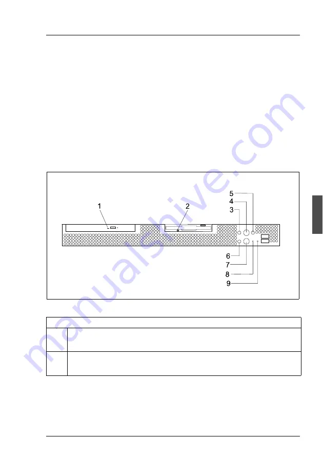
Figure 15: Operating and indicator elements on the front

Indicators on the accessible drives

1

CD-ROM access indicator (green)

Lights up green, when the storage medium is being accessed.

2

Floppy disk drive access indicator (green)

Lights up green, when the storage medium is being accessed.

Table 3: Indicators and operating elements on the front

Содержание PRIMERGY RX100

Страница 1: ...ver System Operating Manual Xenia Fierley Fujitsu Siemens Computers GmbH München 81730 München e mail email manuals fujitsu siemens com Tel 089 61001 157 Fax 49 700 372 00000 A26361 K875 Z102 3 7619 Sprachen En Edition April 2004 ...

Страница 2: ...Department Certified documentation according DIN EN ISO 9001 2000 To ensure a consistently high quality standard and user friendliness this documentation was created to meet the regulations of a quality management system which complies with the requirements of the standard DIN EN ISO 9001 2000 cognitas Gesellschaft für Technik Dokumentation mbH www cognitas de Copyright and Trademarks Copyright 20...

Страница 3: ...Introduction Installation Steps Overview Important Notes Hardware Installation Preparation for Use Operation Problem Solutions and Tips Property and Data Protection Related publications and Index ...

Страница 4: ......

Страница 5: ... the Rack 23 4 3 1 Requirements of the Rack 23 4 3 2 Preparing the Server 28 4 3 3 Mounting into the PRIMECENTER or into the DataCenter Rack 30 4 3 4 Mounting in the Classic Rack 32 4 3 5 Mounting in 3rd Party Racks 34 4 3 6 Mounting Removing the Server 35 4 4 Connecting Devices to the Server 37 4 4 1 Connecting the Monitor 38 4 5 Connecting the Server to the Mains 39 4 6 Instructions on Connectin...

Страница 6: ...ring Stripes Across the Monitor 53 6 5 No Monitor Display or Display Drifts 53 6 6 No Mouse Pointer Displayed on the Monitor 53 6 7 Floppy Disk Cannot be Read or Written onto 54 6 8 Time and or Date are Incorrect 54 6 9 System Fails to Boot 54 6 10 Error Messages on the Monitor 54 7 Property and Data Protection 55 7 1 BIOS Setup security functions 55 Related publications 57 Index 59 ...

Страница 7: ...t HU in the rack 1 1 Overview of the Documentation I PRIMERGY manuals are available in PDF format on the ServerBooks CD The ServerBooks CD is part of the ServerStart Bundle delivered with each server system The PDF files for the manuals can also be downloaded free of charge from the Internet The overview page showing the online documentation available in the Internet can be found via the URL http ...

Страница 8: ...ServerBooks CD Setup Utility D1483 manual PDF file available on the ServerBooks CD ServerStart Bundle includes the ServerStart CD the ServerBooks CD and the print version of the manual ServerStart Bundle The PDF file of the manual is also available on the ServerBooks CD I If you need a backup of the ServerBooks CD send the details of your server via email address Reklamat PC LOG fujitsu siemens co...

Страница 9: ...oltage in the range from 100 V 127 V and 200 V 240 V High Level of Availability and Reliability When memory data are accessed 1 bit errors in the main memory are recog nized and automatically corrected with the ECC Error Correcting Code method ASR R Automatic Server Reconfiguration and Restart restarts the system in the case of an error and automatically hides the defective system components The P...

Страница 10: ...ed publications on page 57 ServerStart You can configure the PRIMERGY server quickly and precisely with the Server Start software provided User guided menus are available for installing the server operating systems Service and Support PRIMERGY server are service friendly and modular thus enabling quick and simple maintenance The flash EPROM programme supplied with the Fujitsu Siemens utilities sup...

Страница 11: ...describes activities that must be performed in the order shown V CAUTION pay particular attention to text marked with this symbol Failure to observe this warning may endanger your life damage the server or lead to loss of data I supplementary information remarks and tips follow this symbol Table 1 Notational Conventions Rated voltage range 100 V 127 V 200 V 240 V Rated frequency 50 Hz 60 Hz Max ra...

Страница 12: ...950 3rd Ed CAN CSA 22 2 No 60950 3rd Ed Electromagnetic Compatibility standard power supply FCC class A VCCI class A JEIDA C Tick class A CNS 13438 class A Emitted interference EN 55022 class A Harmonic current EN 61000 3 2 Flicker EN 61000 3 3 Noise immunity EN 55024 CE label according to EU directives Low Voltage Directive 73 23 EWG Electromagnetic Compatibility 89 336 EEC Product safety Width 4...

Страница 13: ... section 3 2 Temperature Operation 3K2 Transport 2K2 10 C 35 C 25 C 60 C Relative humidity 10 85 CPU 3 06 GHz Sound power level LWAd ISO 9296 5 8B standby 6 0 B operating Sound pressure level at bystander position LpAm ISO 9296 45 dB A standby 45 dB A operating CPU up 3 06 GHz Sound power level LWAd ISO 9296 6 03 B standby 6 25 B operating Sound pressure level at bystander position LpAm ISO 9296 5...

Страница 14: ......

Страница 15: ...to the section Connecting Devices to the Server on page 37 and section Instructions on Connecting and Discon necting Cables on page 40 Ê Connect the system to the line voltage see section Connecting the Server to the Mains on page 39 Ê Make yourself familiar with the operating and indicator elements on the front and on the rear side of the server see section Operating and Indicator Elements on pag...

Страница 16: ......

Страница 17: ...g electronic office machines for use in an office environment If you have any questions contact your sales outlet or our customer service centre V CAUTION The actions described in these instructions should only be performed by technicians service personnel or technical specialists Equipment repairs should only be performed by qualified staff Any failure to observe the guidelines in this manual cou...

Страница 18: ...network with the IEC309 connector the public power supply protection must comply with the requirements for the non industrial public power supply networks for the type A connector The server automatically adjusts to a mains voltage between 100 V to 127 V and or 200 V to 240 V The server may be place in operation only if the mains voltage range set on the server corresponds to the local mains volta...

Страница 19: ...operation of the device in accordance with IEC 60950 DIN EN 60950 is only ensured if the casing is completely assembled and the rear covers for the installation openings have been put in place electric shock cooling fire protection interference suppression Install only system expansions that satisfy the requirements and rules governing safety and electromagnetic compatibility and relating to telec...

Страница 20: ...disposed of in accordance with local regulations concerning special waste Replace the lithium battery on the system board in accordance with the instructions in the technical manual for the system board see Related publications on page 57 All batteries containing pollutants are marked with a symbol a crossed out garbage can In addition the marking is provided with the chemical symbol of the heavy ...

Страница 21: ...cause imbalance Damaged and imbalanced CDs can break at high drive speeds data loss Under certain conditions sharp edged pieces of broken CDs can penetrate the cover of the drive cause damage to the device and be thrown out of the device therefore causing personal injury on uncovered body parts particularly to the face or neck I To protect the CD DVD ROM drive and prevent mechanical damage as well...

Страница 22: ...efore working The equipment and tools you use must be free of static charge Remove the power plug from the power socket before inserting or removing components containing ESDs Always hold components with ESDs by their edges Do not touch any exposed pins or conductors on a component Use a grounding cable designed for this purpose to connect yourself to the system unit as you install components Plac...

Страница 23: ...C rules and meets all requirements of the Canadian Interference Causing Equipment Standard ICES 003 for digital apparatus These limits are designed to provide reasonable protection against harmful interference in a residential installation This equipment generates uses and can radiate radio frequency energy and if not installed and used in strict accordance with the instructions may cause harmful ...

Страница 24: ...tion or attachment of connecting cables and equipment other than those specified by Fujitsu Siemens Computers The correction of interferences caused by such unauthorized modification substitution or attachment will be the responsibility of the user The use of shielded I O cables is required when connecting this equipment to any and all optional peripheral or host devices Failure to do so may viola...

Страница 25: ...eceives power from an industrial public power supply network with the IEC309 connector the public power supply protection must comply with the requirements for the non industrial public power supply networks for the type A connector 3 6 Environmental Protection Environmentally friendly product design and development This product has been designed in accordance with standards for environmen tally f...

Страница 26: ...ment regulations Do not throw lithium batteries into the household waste They must be disposed of in accordance with local regulations concerning special waste Notes on labeling plastic housing parts Please avoid attaching your own labels to plastic housing parts wherever possible since this makes it difficult to recycle them Take back recycling and disposal For details on take back and reuse of d...

Страница 27: ...ation steps are described in detail in other sections of this chapter Ê Unpacking the server see next section Unpacking the Server Ê Mounting the server into the rack see the layout arrangement created with System Architect on the order lists Ê Cabling the server Please also refer to the section Instructions on Connecting and Disconnecting Cables on page 40 Ê Connect the server to the power supply...

Страница 28: ...It may be required for transportation at some later date Ê Unpack all the individual parts Ê Check the contents of the package for visible transport damage Ê Check whether the delivery agrees with the details in the delivery note The identification rating plate is located on the rear area on the server If you find transport damage or inconsistencies between the contents of the package and the deli...

Страница 29: ...s Proceed as follows Ê Close all applications and shut down the operating system in a orderly manner Ê Switch OFF the server Ê Disconnect all cables from the server Ê Remove the server 4 3 1 Requirements of the Rack The rack systems of the Fujitsu Siemens Computers GmbH PRIMECENTER Rack DataCenter Rack and 19 Inch Classic Rack support fully the instal lation of the PRIMERGY server systems The inst...

Страница 30: ...ment within the lateral rack area DataCenter Rack Frontally bolted telescopic rails or sliding rails except within the rear left area where a support bracket is used Extended cable management within the lateral rack area 19 Inch Classic Rack Directly laterally bolted telescopic rails or sliding rails Cable management by using an articulated cable carrier The mounting of the corresponding rails in ...

Страница 31: ... rack rear side A rack depth comparison PRIMECENTER Rack 940 1000 mm B rack width comparison PRIMECENTER Rack 700 mm C clearance of the 19 inch installation level C1 front 19 inch installation level C2 rear 19 inch installation level D area for cable routing cable area depth and ventilation E area for front panel and ventilation F right and left area for support systems P PRIMERGY installation dep...

Страница 32: ...26 A26361 K875 Z102 3 7619 Installing Removing the Server into the Rack Hardware Installation Figure 2 Mechanical conditions ...

Страница 33: ... linear alignment to ensure an adjustment to different rack depths No support of the cable management delivered with the mounting kit Climatic conditions For the air discharge ventilation of the installed server ensure that in the rack from front to rear the air flow is accessible In principle the ventilation concept plans that the necessary cooling is reached by the horizontal self ventilation of...

Страница 34: ...ws on each side 1 to the frontal mounting bracket lower row of holes on the server as shown in figure 3 Ê Mount two cable holders 2 on each support plate The mounting studs of the cable holders must lock into position of the designated holes on the support plate Ê Fasten the support rail with three screws on each side 3 to the frontal mounting bracket lower row of holes on the server as shown in f...

Страница 35: ...d upper server I If two PRIMERGY RX100 s are installed directly on top of each other in the rack the upper server cable arrangement assembly will be turned 180 and mounted into the lower row of holes see figure 4 This guarantees that enough free space is available between the servers for the cable that are to be routed ...

Страница 36: ...ted level with the lower edge of the device Ê Refer to the assembly instructions in the Technical Manual for the corre sponding rack see also Related publications on page 57 I For better orientation the height units are marked on the support uprights only PRIMECENTER Rack Ê Mount the support bracket for the appropriate height on the left rear support upright as described in the technical manual of...

Страница 37: ...ote For the other side one end of the rail must be secured at the support bracket Note Two mounting springs each are used in the appropriate openings of the support uprights and or the support bracket see figure 5 on page 30 Ê Adjust if necessary the length of the telescopic rails by using the oblong holes located on each side of the rails Ê Mount the server see section Mounting Removing the Serve...

Страница 38: ...l Manual for the Classic 19 inch Rack see Related publications on page 57 Ê Mark the position of the attachment points for the telescopic rails and for the server front panel on the support uprights one height unit Ê Place the spring nuts to fasten the telescopic rails in the groove of the support uprights at the marked attachment points Ê If necessary adjust the position of the nuts in the groove...

Страница 39: ...oints on the support uprights The fitting bracket 1 is located between the telescopic rail 2 and the support upright 3 Please note that the guide nubs of the fitting bracket must fit into a hole in the support upright next to the spring nut Ê Secure the two telescopic rails in the rack at the left and right support uprights 4 Ê Mount the server see section Mounting Removing the Server on page 35 ...

Страница 40: ...tion and or the climatic conditions for assistance V CAUTION With the installation in 3rd Party Rack ensure that in the rack from front to rear the air flow is accessible Ê Mount the necessary manufacturer original parts like support bracket or cable management I Sometimes a series of parts from the delivered mounting kit cannot be used because original parts of the 3rd Party Rack are to be used Ê...

Страница 41: ... 3 6 Mounting Removing the Server Figure 9 Mounting the server Ê Lift the server onto the two telescopic rails Ê Slide the server into the rack Ê Place the cage nuts for fastening the front panel in the corresponding holes of the front support uprights and fasten the server using two thumb screws ...

Страница 42: ...vailable for the server Before removing the server from the rack all cables connected on the server must be unpluged from the sockets Please note the instructions in section Installing Removing the Server into the Rack on page 23 Figure 10 Removing the server Ê Press in the safety springs 1 on both telescopic bars and carefully remove the server from the rack 2 ...

Страница 43: ...ilable on your server depends on the PCI boards installed The standard ports figure 11 on the rear are marked with symbols and some are color coded Figure 11 Ports on the rear Two additionally USB ports are located on the front of the server see 1 and 2 on figure 12 on page 38 1 USB port 5 LAN port A 10 100Mbps 2 Mouse port PS 2 green 6 LAN port B 1 Gbps 3 Keyboard port PS 2 purple 7 Serial port C...

Страница 44: ...bles to the server and peripherals 4 4 1 Connecting the Monitor Ê Plug the data cable of the monitor into the monitor port Figure 13 Connecting the monitor to the mains voltage Ê Connect the power cable of the monitor to a grounded mains outlet of the in house mains and or into the mains socket strip of the rack V CAUTION The rated current for the monitor can be found on the technical data label o...

Страница 45: ...127 V and or 200 V to 240 V The server may be place in operation only if the mains voltage range set on the server corresponds to the local mains voltage Figure 14 Connecting the server to the line voltage Ê Connect the insulated connector of the power cable to power supply unit of the server 1 and the power plug to a grounded mains outlet 2 of the in house mains and or into the mains socket strip...

Страница 46: ...ff all power and equipment switches Ê Pull all power plugs out of grounded power sockets Ê Plug all cables into the server and peripherals Secure the data transmission cable connections e g nut retention Ê Plug all data communication cables into the utility sockets Ê Plug all power cables into the grounded power sockets Disconnecting cables Ê Turn off all power and equipment switches Ê Pull all po...

Страница 47: ...ator Elements 5 1 1 The Front Figure 15 Operating and indicator elements on the front Indicators on the accessible drives 1 CD ROM access indicator green Lights up green when the storage medium is being accessed 2 Floppy disk drive access indicator green Lights up green when the storage medium is being accessed Table 3 Indicators and operating elements on the front ...

Страница 48: ...View and his status is also reported to ServerView 5 Global Error indicator amber Does not light when the system is ok No service incident or critical event has occurred Flashes amber when a critical event has occurred Users can check BIOS Setup system and eventlog or via ServerView for event details The indicator also flashes in standby mode Lights amber when a prefailure event has been recognize...

Страница 49: ...button does not disconnect the server from the mains voltage To completely disconnect it from the mains voltage remove the power plug from the socket 8 RST Reset button Pressing the reset button with a pointed object e g a bent paperclip reboots the system 9 NMI NMI button Pressing the NMI button with a pointed object e g a bent paperclip shuts the operating system down immediately I Please do not...

Страница 50: ...anel lights up the integrated identification indicator on the front and the identification indicator on the rear of the server The two identification indicators are synchronized Lights up blue when the system has been selected by pressing the service button To deactivate press again the button The indicator can be selected also via ServerView and his status is also reported to ServerView Table 4 I...

Страница 51: ...ils The indicator also flashes in standby mode Lights amber when a prefailure event has been recognized Users can check system and eventlog or via ServerView for event details The indicator also lights in standby mode If the event is still acute after a power failure the indicator is activated after the restart 3 LAN indicators Each LAN connector is equipped with a green and a yellow indicator The...

Страница 52: ...lation disk in the corresponding drive Ê Press the ON OFF button position 7 in figure 15 on page 41 Ê Follow the instructions on the monitor see also section Configuration with ServerStart on page 48 and or section Configuration without ServerStart on page 48 System already installed Ê Press the ON OFF button position 7 in figure 15 on page 41 The server is switched ON performs a system test and b...

Страница 53: ... to normal operation Other ON OFF possibilities In addition to the ON OFF button the server can be switched ON and OFF in the following ways Specified switch On time switch OFF time The server is switched ON or OFF at a time specified in the ServerView programme Ring indicator The server is switched ON via an internal or external modem Wakeup On LAN WOL The server is switched ON by a command via t...

Страница 54: ...orresponding CD booklet see Related publications on page 57 I Descriptions of operating systems not covered in the RAID controller manual are provided in the appropriate readme files on the driver diskettes If you use ServerStart you can skip the following sections on how to configure the server and install the operating system Continue with section Cleaning the Server on page 49 5 3 2 Configurati...

Страница 55: ...tility D1483 see also Related publications on page 57 5 4 Cleaning the Server V CAUTION Switch the server off and pull the power plug out of the grounded contact power socket Do not clean any interior parts yourself leave this job to a service technician Do not use any cleaning agents that contain abrasives that may corrode plastic Ensure that no liquid enters the system Ensure that the ventilatio...

Страница 56: ......

Страница 57: ...steps and the circumstances that led to the fault Note also any error message which may have been displayed Ê Switch the server OFF Ê Contact our Service organization see Warranty under Related publica tions on page 57 6 1 Power ON Indicator Remains Dark The power ON indicator remains dark after switching ON Power cable not connected correctly Ê Make sure that the power cable is correctly connecte...

Страница 58: ...r the appropriate password Brightness control is set too dark Ê Adjust the brightness control to increase the brightness For detailed infor mation please refer to the operating manual supplied with your monitor Power cable or monitor cable not connected Ê Switch OFF the monitor and the server Ê Check whether the power cable is properly connected to the monitor and to the power socket Ê Check wheth...

Страница 59: ...y 6 5 No Monitor Display or Display Drifts The wrong horizontal frequency and or resolution has been selected for the monitor or for the application programme Ê Find out which horizontal frequency your monitor supports You will find the horizontal frequency also known as line frequency or horizontal deflection frequency in the documentation for your monitor Ê Refer to the documentation for your op...

Страница 60: ...ed see technical manual for system board at the PRIMERGY ServerBooks CD 6 8 Time and or Date are Incorrect Ê Set the time and or date in the operating system or in the Setup Utility D1483 I If the time and date are repeatedly wrong when you switch on your server you must change the lithium battery Contact our Service group 6 9 System Fails to Boot The system will not boot after installing a new ha...

Страница 61: ... combining these options you can achieve optimum protection for your system I You will find a detailed description of the System Security menu and how to assign passwords in the manual for the Setup Utility D1483 on the ServerBooks CD see also Related publications on page 57 Preventing unauthorized BIOS Setup calls You can activate this protection by setting a supervisor password in the System Sec...

Страница 62: ......

Страница 63: ... online documentation available in the Internet can be found via the URL http manuals fujitsu siemens com choose intel based servers PRIMERGY ServerBooks 1 Safety and Ergonomics 2 Warranty 3 19 inch rack Technical Manual 4 DataCenter Rack Technical Manual 5 PRIMECENTER Rack Technical Manual 6 PRIMERGY ServerStart Bundle User Manual 7 ServerView Server Management User Manual 8 RemoteView User Manua...

Страница 64: ......

Страница 65: ...2 devices connecting to the server 37 disconnecting cables 40 disposal of devices 20 drive indicators 41 E ECC 3 electrical data 5 electromagnetic compatibility 6 17 EMC 6 environmental conditions 7 environmental protection 19 error display drifts 53 flickering stripes on screen 53 floppy disk cannot be read or written 54 no mouse pointer 53 screen remains dark 52 server switches off 52 system doe...

Страница 66: ...ling server 23 L LAN indicator 45 light emitting diode LED 14 lithium battery 14 low voltage directive 6 17 M mains voltage connecting the server 39 meaning of the symbols 5 model rating plate 22 monitor display drifts 53 flickering 53 no display on screen 53 screen dark 53 mouse no mouse pointer on the screen 53 N NMI button 43 noise level 7 notational conventions 5 note on the laser 14 notes on ...

Страница 67: ...protection 55 dimensions 6 electrical data 5 environmental conditions 7 fitting in the rack 23 height units 30 32 indicators 41 42 installing 23 keyboard port 37 LAN port 37 monitor port 37 mouse port 37 NMI button 43 noise level 7 ON OFF button 43 operation 41 operator panel 41 ports 37 prepare 28 property protection 55 reset button 43 safety standards 5 6 serial port 37 setting up 41 standards 6...

Страница 68: ...e 47 System Architekt 21 System board 3 system does not boot 54 T take back of devices 20 target group 1 technical data 5 telescopic bar 28 telescopic rail 31 33 time wrong 54 transport damage 22 troubleshooting server 51 U unpacking server 22 V ventilation clearance 6 W weight 6 ...

Страница 69: ...System A26361 K875 Z102 3 7619 Comments Suggestions Corrections Submitted by Fujitsu Siemens Computers GmbH User Documentation 81730 München Germany Fax 49 700 372 00000 email manuals fujitsu siemens com http manuals fujitsu siemens com ...

Страница 70: ......

Страница 71: ...System A26361 K875 Z102 3 7619 Comments Suggestions Corrections Submitted by Fujitsu Siemens Computers GmbH User Documentation 81730 München Germany Fax 49 700 372 00000 email manuals fujitsu siemens com http manuals fujitsu siemens com ...

Страница 72: ......

Страница 73: ...tsu com Copyright Fujitsu Technology Solutions 2009 Hinweise zum vorliegenden Dokument Zum 1 April 2009 ist Fujitsu Siemens Computers in den alleinigen Besitz von Fujitsu übergegangen Diese neue Tochtergesellschaft von Fujitsu trägt seit dem den Namen Fujitsu Technology Solutions Das vorliegende Dokument aus dem Dokumentenarchiv bezieht sich auf eine bereits vor längerer Zeit freigegebene oder nic...

Отзывы: