Fujitsu PRIMERGY GX2570 M6 Скачать руководство пользователя страница 268

Status

Description

flashing red at
4 Hz

Identification of drive with RSTe support

green on

NVMe device can be removed safely

flashing amber at
1 Hz

Attention state, do not remove NVMe drive.

Activity indicator (2)

Status

Description

blue on

SAS/NVMe drive is installed.

flashing blue

Drive is being accessed.
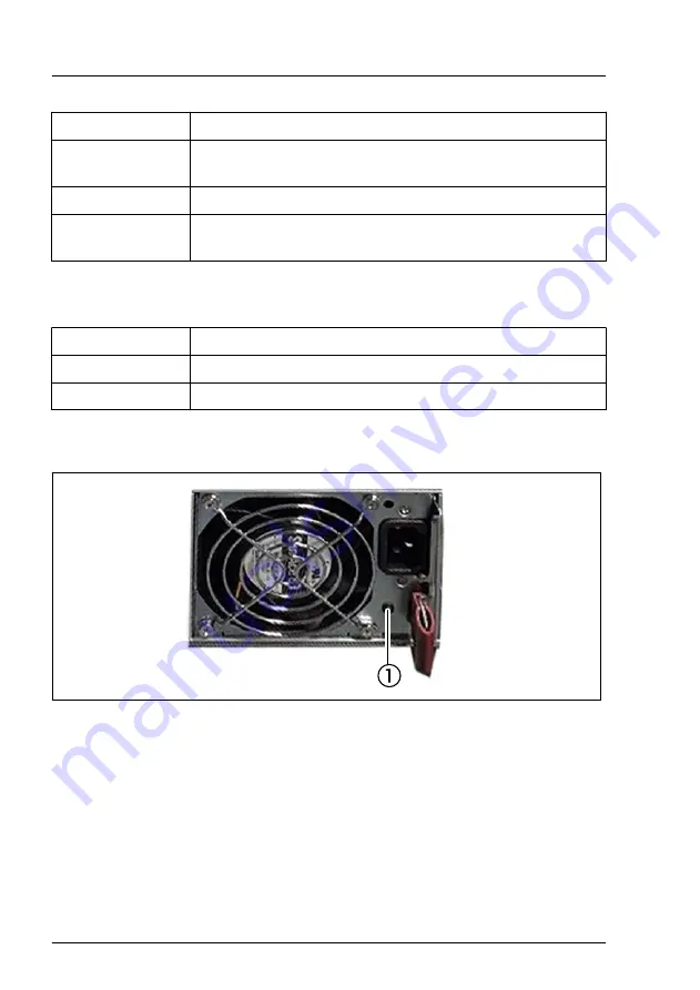
17.2.3.2

Indicator on hot-plug PSU

Figure 218: Indicator on hot-plug PSU

1

PSU status indicator

Appendix A

268

Upgrade and Maintenance Manual

GX2570 M6

Содержание PRIMERGY GX2570 M6

Страница 1: ...FUJITSU Server PRIMERGY GX2570 M6 Upgrade and Maintenance Manual Upgrade and Maintenance Manual English 04 2021 ...

Страница 2: ...tas de Copyright and Trademarks Copyright 2021 FUJITSU LIMITED All rights reserved Delivery subject to availability right of technical modifications reserved All hardware and software names used are trademarks of their respective manufacturers The contents of this manual may be revised without prior notice Fujitsu assumes no liability for damages to third party copyrights or other rights arising f...

Страница 3: ...tic capacitors used in the printed circuit board assemblies of the product and in the mouse and keyboard are limited life components Use of these components beyond their operating life may result in electrolyte leakage or depletion potentially causing emission of foul odor or smoke As a guideline in a normal office environment 25 C operating life is not expected to be reached within the maintenanc...

Страница 4: ...ensuring the level of safety demanded of such use Please consult the sales staff of Fujitsu if intending to use this product for high safety use Measures against momentary voltage drop This product may be affected by a momentary voltage drop in the power supply caused by lightning To prevent a momentary voltage drop the use of an uninterruptible power supply is recommended This notice follows the ...

Страница 5: ...e of HDD used For more information on the usage and operation conditions of each available type of HDD see the following internet address https jp fujitsu com platform server primergy harddisk Only for Japan Shielded LAN cables should be used in this product UK Importer information Fujitsu Services Limited 22 Baker Street London W1U 3BW United Kingdom GX2570 M6 Upgrade and Maintenance Manual ...

Страница 6: ...Version history Issue number Issue date Description V 1 0 04 2021 Initial release Upgrade and Maintenance Manual GX2570 M6 ...

Страница 7: ...nment of unit categories 18 2 2 2 Customer Replaceable Units CRU 18 2 2 3 Upgrade and Repair Units URU 19 2 2 4 Field Replaceable Units FRU 20 2 3 Average task duration 21 2 4 Tools you need at hand 22 2 5 Documentation overview 22 2 5 1 Downloading manuals 22 2 5 2 List of documents 23 3 Important information 25 3 1 Introduction 25 3 2 Safety instructions 25 3 2 1 Basic safety instructions 25 3 2...

Страница 8: ...res 39 4 1 Using diagnostic information 39 4 1 1 Proceeding 39 4 1 2 Locating the defective server 39 4 1 3 Locating the defective component 39 4 2 Shutting down the server 40 4 3 Disconnecting the power cord 40 4 4 Getting access to the component 41 4 4 1 Safety notes 41 4 4 2 Extending the server out of the rack 41 4 4 3 Removing the server from the rack 43 4 5 Reassembling 45 4 5 1 Safety notes...

Страница 9: ...13 1 Removing the cross bar 63 4 13 2 Installing the cross bar 65 5 Basic software procedures 67 5 1 Starting the maintenance task 67 5 1 1 Disabling the boot watchdog 67 5 1 2 Verifying and configuring the backup software solution 67 5 1 3 Backing up the setting information of BIOS or BMC 68 5 1 4 Switching on the ID indicators 68 5 2 Completing the maintenance task 68 5 2 1 Updating or recoverin...

Страница 10: ... 86 7 3 1 2 5 inch HDD SSD and 2 5 inch installation frame 86 7 4 2 5 inch HDD SSD configurations 88 7 4 1 Overview of configurations 88 7 4 1 1 Configuration with up to 10 HDD SSD modules 88 7 4 2 Installing 2 5 inch HDD SSD modules 90 7 4 3 Removing 2 5 inch HDD SSD modules 92 7 4 4 Replacing a 2 5 inch HDD SSD module 94 7 4 5 Replacing the 6x 2 5 inch HDD backplane front 96 7 4 6 Replacing the ...

Страница 11: ...e slots 130 9 5 1 Installing an expansion card 130 9 5 2 Removing an expansion card 132 9 5 3 Replacing an expansion card 134 9 5 4 Replacing the switch board 135 9 6 Expansion cards in riser modules 141 9 6 1 Installing an expansion card in a riser module 141 9 6 2 Removing an expansion card from a riser module 143 9 6 3 Replacing an expansion card from a riser module 145 9 6 4 Replacing a riser ...

Страница 12: ...tion 166 11 3 Replacing a CPU or heat sink 167 12 Graphic processor GPU 179 12 1 Safety notes 179 12 2 Basic information 179 12 3 Replacing a GPU or heat sink 181 12 4 Replacing the GPU board 185 13 Liquid cooling LC 189 13 1 Basic information 189 13 2 Replacing the CPU or LC kit 193 13 3 Replacing the GPU or LC kit 206 14 Midplane kit 225 14 1 Safety notes 225 Content Upgrade and Maintenance Manu...

Страница 13: ...tion 243 16 3 CMOS battery 244 16 3 1 Replacing the CMOS battery 244 16 4 System board 246 16 4 1 Replacing the system board 246 17 Appendix A 253 17 1 Mechanical overview 253 17 1 1 Server front 253 17 1 2 Server rear 255 17 1 3 Server interior 256 17 2 Connectors and indicators 260 17 2 1 System board 260 17 2 1 1 Connectors and indicators on the system board 260 17 2 2 Server front 263 17 2 2 1...

Страница 14: ...HDD SSD modules 266 17 2 3 Server rear 267 17 2 3 1 Indicators on hot plug HDD SSD modules 267 17 2 3 2 Indicator on hot plug PSU 268 17 2 4 Acoustic indicators 269 17 3 Onboard settings 271 17 4 Minimum startup configuration 272 18 Appendix B 275 18 1 Supplied documents 275 Content Upgrade and Maintenance Manual GX2570 M6 ...

Страница 15: ...aintenance tasks CAUTION The document at hand comprises procedures of a wide range of complexity Check the profile of qualification for technicians before assigning tasks Before you start carefully read Classification of procedures on page 18 1 2 Notational conventions The following notational conventions are used in this manual Text in bold Indicates references to names of interface elements Text...

Страница 16: ...s warning may endanger your life destroy the system or lead to the loss of data Indicates additional information notes and tips Indicates the procedure category in terms of complexity and qualification requirements see Classification of procedures on page 18 Indicates the average task duration see Average task duration on page 21 Introduction 16 Upgrade and Maintenance Manual GX2570 M6 ...

Страница 17: ...available see Tools you need at hand on page 22 2 1 2 Installing optional components The operating manual of your server gives an introduction to server features and provides an overview of available hardware options For the latest information on hardware options see the hardware configurator of your server available online at the following address https www fujitsu com emeia products computing se...

Страница 18: ...roduced in this section Please ask your local Fujitsu service center for more information 2 2 2 Customer Replaceable Units CRU Customer Replaceable Units CRU Customer Replaceable Units are intended for customer self service and may be installed or replaced as hot plug components during operation Components that the customer is entitled to replace may differ according to the service form in his cou...

Страница 19: ...de Units or are available to the customer through customer self service Repair Units For Japan customer allows only upgrade For upgrade units as customer replaceable see https www fujitsu com jp products computing servers primergy Upgrade and repair procedures involve shutting down and opening the server CAUTION The device may be seriously damaged or cause damage if it is opened without authorizat...

Страница 20: ...Maintenance procedures involving Field Replaceable Units must be performed exclusively by Fujitsu service personnel or technicians trained by Fujitsu Please note that unauthorized interference with the system will void the warranty and exempt the manufacturer from all liability Components that are handled as Field Replaceable Units CPU replacement GPU replacement HDD backplane Front panel board Sy...

Страница 21: ...ificantly Software tasks necessary before maintenance see Starting the maintenance task on page 67 Rack removal disassembly yes Making the server available removing the server from the rack if applicable Transport no Transporting the server to the service table where required depends on local customer conditions Maintenance procedures yes Maintenance procedures including preliminary and concluding...

Страница 22: ...edure 2 5 Documentation overview 2 5 1 Downloading manuals Maintenance procedures may include references to additional documentation Ensure to store all printed manuals enclosed with your server in a save place for future reference When preparing the maintenance task ensure that all required manuals are available see Table 2 If applicable download the manual from the following address https suppor...

Страница 23: ...ion on configurable BIOS options and parameters available online FUJITSU Server PRIMERGY GX2570 M6 Disassembly and Recycling Instructions Instructions for disassembling and recycling the server available online Software documentation BMC web Interface user guide available online Illustrated Spares catalog Spare parts identification and information system not valid for Japan available for online us...

Страница 24: ...ons for recycling Service Desk leaflet サポート サービス for Japan Additional documentation RAID documentation and NVMe User Guide available online at https support ts fujitsu com For Japan https www fujitsu com jp products computing servers primergy manual Third party documentation Operating system documentation online help Peripherals documentation Table 2 List of documents Before you start 24 Upgrade a...

Страница 25: ...server meets the relevant safety regulations for IT equipment If you have any questions about whether you can install the server in the intended environment please contact your sales outlet or our customer service team The actions described in this manual shall be performed by technical specialists A technical specialist is a person who is trained to install the server including hardware and softw...

Страница 26: ... packaging that protects it from impacts and jolts In Japan and APAC transporting the server in its original packaging does not apply 3 2 3 Installation and operation This server should not be operated in ambient temperatures above 35 C For servers with Advanced Thermal Design the ambient temperature can increase to 40 C or 45 C If the server is integrated into an installation that draws power fro...

Страница 27: ...FTP Cat5 or higher is recommended Use of unshielded or badly shielded cables may lead to increased emission of interference and or reduced fault tolerance of the device Ethernet cabling has to comply with EN 50173 and EN 50174 1 2 standards or ISO IEC 11801 standard respectively The minimum requirement is a Category 5 shielded cable for 10 100 Ethernet or a Category 5e cable for Gigabit Ethernet R...

Страница 28: ...ied in the operating manual for the monitor Otherwise you may damage your monitor If you are in any doubt contact your sales outlet or customer service center Only valid for non hot plug components Before installing removing internal components to from the server turn off the server all peripheral devices and any other connected devices Also unplug all power cords from the power outlet Failure to ...

Страница 29: ...insert the battery the right way round The battery used in this server may present a fire or chemical burn hazard if mistreated Do not disassemble heat about 100 C 212F or incinerate the battery Replace the lithium battery on the system board in accordance with the instructions in the corresponding Upgrade and Maintenance Manual chapter System board and components CMOS battery All batteries contai...

Страница 30: ...etallic items such as paper clips entering a drive Shocks and vibrations are also to be avoided Do not insert any objects other than the specified CDs DVDs BDs Do not pull on press hard or otherwise handle the CD DVD BD tray roughly Do not disassemble the ODD Before use clean the ODD tray using a soft dry cloth As a precaution remove disks from the ODD when the drive is not to be used for a long t...

Страница 31: ...as exposed to prolonged direct sunlight or near heating appliances are to be avoided You can prevent damage from the ODD and the CDs DVDs BDs as well as premature wear of the disks by observing the following suggestions Only insert disks in the drive when needed and remove them after use Store the disks in suitable sleeves Protect the disks from exposure to heat and direct sunlight 3 2 6 Laser inf...

Страница 32: ...D modules and connect it to an unpainted conducting metal part of the server Any devices or tools that are used must be free of electrostatic charge Wear a suitable grounding cable that connects you to the external chassis of the server Always hold ESD modules at the edges or at the colored touch points Do not touch any connectors or conduction paths on an ESD module Place all the components on a ...

Страница 33: ...ransporting the server in its original packaging does not apply Do not unpack the server until it is at its installation location If you need to lift or transport the server ask other people to help you Never lift or carry the server by the handles or the Quick Release Levers QRLs on the front panel Important information GX2570 M6 Upgrade and Maintenance Manual 33 ...

Страница 34: ...ended from the rack there is a risk that the rack could tip over See the safety information of the rack and the warning label If the server rack is intended for permanent connection to the mains only an authorized specialist electrician is allowed to work Please follow the regulation of each country If the server is integrated into an installation that draws power from an industrial power supply n...

Страница 35: ...al unless otherwise specified herein The statement for other products will appear in the accompanying documentation NOTE This equipment has been tested and found to comply with the limits for a Class A digital device pursuant to Part 15 of the FCC rules and meets all requirements of the Canadian Interference Causing Equipment Standard ICES 003 for digital apparatus These limits are designed to pro...

Страница 36: ...I O cables is required when connecting this equipment to any and all optional peripheral or host devices Failure to do so may violate FCC and ICES rules 3 5 Environmental protection Environmentally friendly product design and development This product has been designed in accordance with the Fujitsu standard for environmentally friendly product design and development This means that key factors suc...

Страница 37: ...They can be returned free of charge to the manufacturer dealer or an authorized agent for recycling or disposal All batteries containing pollutants are marked with a symbol a crossed out garbage can They are also marked with the chemical symbol for the heavy metal that causes them to be categorized as containing pollutants Cd Cadmium Hg Mercury Pb Lead Labels on plastic casing parts Please avoid s...

Страница 38: ...and is valid across the EU When returning your used device please use the return and collection systems available to you More information can be found at https ts fujitsu com recycling Details regarding the return and recycling of devices and consumables within Europe can also be found in the Returning used devices manual via your local Fujitsu branch or at https ts fujitsu com recycling Important...

Страница 39: ...ess the ID button on the front panel board Remember to switch off the ID indicator after the maintenance task has been concluded successfully 4 1 3 Locating the defective component Indicators on the components and onboard indicators on the system board allow you to identify the defective component Possibilities to get more information about the defective component Checking the System Event Log SEL...

Страница 40: ...e Terminate all applications Perform the required procedures described in the preliminary steps of each upgrade or maintenance task Shut down the server If the system is running an ACPI compliant operating system OS pressing the On Off button will perform a graceful shutdown 4 3 Disconnecting the power cord Figure 2 Disconnecting the power cords Disconnect the power cord from the PSU Basic hardwar...

Страница 41: ...and to prevent fires For more information see Important information on page 25 4 4 2 Extending the server out of the rack CAUTION Use the anti tilt plate to prevent the rack from tipping when installing the rack Pulling the server out of the rack without having installed the anti tilt plate may cause the rack to tip over Be careful not to pinch fingers or clothes when sliding out the server or pus...

Страница 42: ...ut of the rack Pull the server with the installed rack rails out of the rack as far as possible CAUTION Do not use the extended server as a surface on which to put things or as a work surface and strictly avoid leaning on or against it Basic hardware procedures 42 Upgrade and Maintenance Manual GX2570 M6 ...

Страница 43: ...AUTION At least two people are needed to lift the server out of the rack cabinet For Japan see 安全上のご注意 For configurations below 32 kg At least two people are needed to lift the server out of the rack cabinet For configurations below 55 kg At least three people are needed to lift the server out of the rack cabinet For configurations above 55 kg At least four people are needed to lift the server out...

Страница 44: ...than 21 kg and is to be removed above the height of 25 U When using a lifter this removal procedure needs to be carried out by maintenance personnel Figure 5 Lifting the server Lift the server out of the rack rails and place it on an even surface Basic hardware procedures 44 Upgrade and Maintenance Manual GX2570 M6 ...

Страница 45: ...and to prevent fires For more information see Important information on page 25 4 5 2 Installing the server in the rack CAUTION At least two people are needed to position the server on the rack rails For Japan see 安全上のご注意 For configurations below 32 kg At least two people are needed to lift the server into the rack cabinet For configurations below 55 kg At least three people are needed to lift the ...

Страница 46: ...e server weighs more than 50 kg The server weighs more than 21 kg and is to be installed above the height of 25 U When using a lifter this installation procedure needs to be carried out by maintenance personnel Figure 6 Lifting the server onto the rack rails Lift the server onto the rack rails Basic hardware procedures 46 Upgrade and Maintenance Manual GX2570 M6 ...

Страница 47: ... Push the server as far as it will go into the rack Figure 8 Fastening the server in the rack Fasten the server in the rack with the two knurled screws Connect all cables except the power cord to the server rear Basic hardware procedures GX2570 M6 Upgrade and Maintenance Manual 47 ...

Страница 48: ...o the local mains voltage Figure 9 Connecting the power cord Connect the power cord to the PSU Connect the main plug to an power outlet of the rack socket strip Ensure that the status indicator on the PSU is lit green see Indicator on hot plug PSU on page 268 It will take about 60 seconds until the server can be powered on Basic hardware procedures 48 Upgrade and Maintenance Manual GX2570 M6 ...

Страница 49: ...cooling requirements the server must not run while the top cover is removed For more information see Important information on page 25 Press the On Off button to start up the server Ensure that the power on indicator is lit green 4 8 Handling the CPU node 4 8 1 Removing the CPU node Figure 10 Loosening the screw Loosen the screw see circle Basic hardware procedures GX2570 M6 Upgrade and Maintenance...

Страница 50: ... the CPU node by the handles see circles Pull out the CPU node by pressing the locking levers see close ups 4 8 2 Installing the CPU node Figure 12 Installing the CPU node Basic hardware procedures 50 Upgrade and Maintenance Manual GX2570 M6 ...

Страница 51: ...l the locking levers engage Figure 13 Fastening the screw Fasten the screw see circle 4 9 Handling the GPU node 4 9 1 Removing the GPU node Figure 14 Loosening the screws Loosen the two screws see circles Basic hardware procedures GX2570 M6 Upgrade and Maintenance Manual 51 ...

Страница 52: ... 15 Removing the GPU node Hold the GPU node by the handles see circles Pull out the GPU node by pressing the locking levers see close ups Basic hardware procedures 52 Upgrade and Maintenance Manual GX2570 M6 ...

Страница 53: ...igure 16 Installing the GPU node Hold the GPU node by the handles see circles Slide in the GPU node until the locking levers engage Figure 17 Fastening the screws Basic hardware procedures GX2570 M6 Upgrade and Maintenance Manual 53 ...

Страница 54: ...s see circles 4 10 Handling the switch board tray 4 10 1 Removing the switch board tray Figure 18 Loosening the screws Loosen the two screws see circles Basic hardware procedures 54 Upgrade and Maintenance Manual GX2570 M6 ...

Страница 55: ...tch board tray by the handles see circles Pull out the switch board tray in the direction of the arrow 4 10 2 Installing the switch board tray Figure 20 Installing the switch board tray Basic hardware procedures GX2570 M6 Upgrade and Maintenance Manual 55 ...

Страница 56: ...oard tray by the handles Install the switch board tray in the direction of the arrow Figure 21 Fastening the screws Fasten the two screws see circles Basic hardware procedures 56 Upgrade and Maintenance Manual GX2570 M6 ...

Страница 57: ... 11 Handling the riser module 4 11 1 Removing the riser module Figure 22 Opening the locks Open the two locks Pull out the two locks Basic hardware procedures GX2570 M6 Upgrade and Maintenance Manual 57 ...

Страница 58: ...Figure 23 Disconnecting the power cable Disconnect the power cable see circles Basic hardware procedures 58 Upgrade and Maintenance Manual GX2570 M6 ...

Страница 59: ...Figure 24 Removing the riser module Grip the riser module by the holes see circles Remove the riser module Basic hardware procedures GX2570 M6 Upgrade and Maintenance Manual 59 ...

Страница 60: ... Installing the riser module Figure 25 Installing the riser module Grip the riser module by the holes see circles Install the riser module Basic hardware procedures 60 Upgrade and Maintenance Manual GX2570 M6 ...

Страница 61: ...e 26 Connecting the power cable Connect the power cable see circles Figure 27 Closing the locks Push in the two locks Close the two locks Basic hardware procedures GX2570 M6 Upgrade and Maintenance Manual 61 ...

Страница 62: ...andling the air duct 4 12 1 Removing the air duct Figure 28 Removing the air duct Remove the three screws 1 Remove the air duct upwards 2 Basic hardware procedures 62 Upgrade and Maintenance Manual GX2570 M6 ...

Страница 63: ...re 29 Installing the air duct Install the air duct 1 Fasten the three screws 2 4 13 Handling the cross bar 4 13 1 Removing the cross bar Figure 30 Removing the screws Basic hardware procedures GX2570 M6 Upgrade and Maintenance Manual 63 ...

Страница 64: ...the screw 2 Figure 31 Note on removing the cross bar It is not necessary to remove the screws inside the orange circle Figure 32 Removing the cross bar Remove the cross bar Basic hardware procedures 64 Upgrade and Maintenance Manual GX2570 M6 ...

Страница 65: ...the recesses on the left and right sides of the cross bar fit into the guiding pins of the chassis see close ups Figure 34 Fastening the screws Fasten the cross bar with one screw at each side 1 Fasten the cross bar with the screw 2 Basic hardware procedures GX2570 M6 Upgrade and Maintenance Manual 65 ...

Страница 66: ...Basic hardware procedures 66 Upgrade and Maintenance Manual GX2570 M6 ...

Страница 67: ...initiate a system reboot before the flash process is complete CAUTION An incomplete firmware upgrade process may render the server inaccessible or result in damaged destroyed hardware Timer settings can be configured in the BIOS Disabling the boot watchdog in the BIOS Enter the BIOS Select the Server Mgmt menu Under Boot Watchdog set the Action setting to Continue Save your changes and exit the BI...

Страница 68: ...1 4 Switching on the ID indicators For easy identification of the server switch on the ID indicators especially when working in a datacenter environment or a server room The ID indicators can also be activated using IPMI Using the ID button on the I O panel Press the ID button on the I O panel to switch on the ID indicators For more information see Indicators on the front panel on page 264 5 2 Com...

Страница 69: ... the server or for the loss of any data resulting from BIOS updates BIOS flash procedure Perform the BIOS flash procedure as described in the BIOS Setup Utility reference manual of your server BIOS recovery procedure Perform the BIOS recovery procedure as described in the BIOS Setup Utility reference manual of your server BMC flash procedure Prepare a USB stick including the bootable BMC firmware ...

Страница 70: ...ocess remove the USB stick and restart the server BMC recovery procedure Prepare a USB stick including the bootable BMC firmware update image Ensure that the server has been shut down and disconnected from the mains see Disconnecting the power cord on page 40 Connect the USB stick containing the BMC firmware to a USB port Connect the server to the mains while pushing the ID button on the front pan...

Страница 71: ...e of a boot controller that may require frequent setup or temporarily for one time configuration When permanently enabling the Option ROM of a controller in a legacy BIOS keep in mind that only two Option ROMs can be activated in the BIOS at a time Enter the BIOS From the Advanced menu select Option ROM Configuration Identify the desired PCI slot and set its Launch Slot OpROM setting to Enabled Sa...

Страница 72: ... settings can be configured in the BIOS Enabling the boot watchdog in the BIOS Enter the BIOS Select the Server Mgmt menu Under Boot Watchdog set the Action setting to Reset Save your changes and exit the BIOS For more information on how to access the BIOS and modify settings see the corresponding BIOS Setup Utility reference manual 5 2 4 Verifying the system time settings This task only applies t...

Страница 73: ...ime If your IT infrastructure relies on universally accepted time standards set the System Time to UTC Universal Time Coordinated instead Greenwich Mean Time GMT can be considered equivalent to UTC Save your changes and exit the BIOS For more information on how to access the BIOS and modify settings see the corresponding BIOS Setup Utility reference manual 5 2 5 Viewing and clearing the System Eve...

Страница 74: ... configuration file in a Linux environment In order to prevent errors caused by changing network device names eth x it is recommended to store the MAC address hardware address of a network interface card in the related NIC configuration file of the Linux OS When replacing a network controller or the system board with onboard LAN controllers in a server running Linux OS the MAC address will change ...

Страница 75: ...roller offers multiple LAN ports it is necessary to update the remaining ifcfg eth x definition files accordingly Update the NIC configuration file to reflect the new card sequence and MAC address 5 2 7 Performing a RAID array rebuild After replacing an HDD that has been combined into a RAID array RAID rebuild will be performed completely unattended as a background process Ensure that the RAID arr...

Страница 76: ...oking for the MAC address of a LAN controller The customer needs to know the new address of the controller When replacing the system board with an onboard LAN controller When adding or replacing a network controller Different controllers send different addresses LAN controller MAC Media Access Control address When replacing a network controller the MAC Media Access Control address will change Ther...

Страница 77: ...IOS setup menu Select the Advanced menu The addresses are displayed at the Advanced menu main page Only network controllers supporting the Command Line Protocol CLP will be displayed LAN controller provide the MAC addresses independent on Legacy Boot or UEFI Boot For more information see the corresponding BIOS reference manual 5 2 9 Switching off the ID identicators The ID indicators can also be d...

Страница 78: ...Basic software procedures 78 Upgrade and Maintenance Manual GX2570 M6 ...

Страница 79: ...ke injuries may result For more information see Important information on page 25 6 2 Basic information AC PSU The server is equipped with four hot plug PSUs that adjust automatically to any mains voltage in the range from 200 V 240 V If one PSU fails the other PSUs ensure that operation can continue uninterrupted and the defective PSU can be replaced during operation hot plug CAUTION The server au...

Страница 80: ...a redundant power supply configuration you need always four PSUs with the same power class Mixed assembly of PSUs from different power classes e g class 1 or class 2 within a system is not supported 6 3 Redundant power supply 6 3 1 Replacing a hot plug PSU Customer Replaceable Unit CRU Hardware 5 minutes Tools tool less Power supply unit PSU 80 Upgrade and Maintenance Manual GX2570 M6 ...

Страница 81: ...ive server on page 39 Check which PSU is defective A PSU is defective when the PSU status indicator lights orange For more information see Indicator on hot plug PSU on page 268 Only when replacing a PSU in a non redundant configuration Shutting down the server on page 40 Remove the power cord from the defective PSU see Disconnecting the power cord on page 40 Power supply unit PSU GX2570 M6 Upgrade...

Страница 82: ... PSU Pull up the locking lever 1 Remove the PSU 2 CAUTION Excessive temperatures could damage system components Never leave the bay for the hot plug PSU empty for more than two minutes during operation Power supply unit PSU 82 Upgrade and Maintenance Manual GX2570 M6 ...

Страница 83: ...bay as far as it will go 1 Pull down the locking lever to insert the PSU completely 2 Ensure that the PSU engages correctly in the bay and is locked in position This is the only way to prevent the PSU from sliding out of its bay and being damaged during transportation Power supply unit PSU GX2570 M6 Upgrade and Maintenance Manual 83 ...

Страница 84: ...e power cord to the new PSU see Connecting the power cord on page 48 Only when replacing a PSU in a non redundant configuration Switching on the server on page 49 Power supply unit PSU 84 Upgrade and Maintenance Manual GX2570 M6 ...

Страница 85: ...DDs If a power failure should occur while the write cache is enabled cached data may be lost When disposing of transferring or returning an HDD or SSD wipe out the data on the drive for your own security Rough handling of HDDs may damage the stored data To cope with any unexpected problems always back up important data When backing up data to another HDD you should make backups on a file or partit...

Страница 86: ...d at the server rear For information on RAID controllers controlling the HDD SSD modules see Expansion cards and riser modules on page 115 7 3 Handling HDDs or SSDs without installation frame 7 3 1 2 5 inch HDD SSD and 2 5 inch installation frame Installing or removing the installation frame is only necessary for Japan Customer Replaceable Unit CRU Hardware 5 minutes Tools tool less Preliminary st...

Страница 87: ...ng the HDD SSD in the installation frame Insert the HDD SSD in the installation frame Ensure that the four holes at the bottom side of the HDD SSD fit in the guiding pins of the installation frame Hard disk drive HDD solid state disk SSD GX2570 M6 Upgrade and Maintenance Manual 87 ...

Страница 88: ...by pressing the figure with your finger see circle Concluding steps No steps needed 7 4 2 5 inch HDD SSD configurations 7 4 1 Overview of configurations 7 4 1 1 Configuration with up to 10 HDD SSD modules The HDD bays can be equipped with up to 10 2 5 inch HDD SSD modules Hard disk drive HDD solid state disk SSD 88 Upgrade and Maintenance Manual GX2570 M6 ...

Страница 89: ...ont view Figure 42 Configuration with four 2 5 inch HDD SSDs rear view Position Component 0 HDD 0 1 HDD 1 2 HDD 2 3 HDD 3 4 HDD 4 5 HDD 5 6 HDD 6 7 HDD 7 8 HDD 8 9 HDD 9 Hard disk drive HDD solid state disk SSD GX2570 M6 Upgrade and Maintenance Manual 89 ...

Страница 90: ...gurations on page 88 Removing a 2 5 inch HDD SSD dummy module The dummy module is the installation frame without an installed HDD SSD Figure 43 Removing a 2 5 inch HDD SSD dummy module Pinch the green release button and open the locking lever 1 Pull the HDD SSD dummy module out of its bay 2 Hard disk drive HDD solid state disk SSD 90 Upgrade and Maintenance Manual GX2570 M6 ...

Страница 91: ... drive bay and carefully push back as far as it will go 1 Close the locking lever to lock the HDD SSD module in place 2 When using a RAID array add the additional HDD SSD to the RAID array Configuring the RAID array see the documentation of the RAID controller used in your configuration see Documentation overview on page 22 Concluding steps No steps needed Hard disk drive HDD solid state disk SSD ...

Страница 92: ...data loss However the removed drive needs to be replaced immediately by an HDD SSD module of the same or larger capacity After replacing the HDD SSD module RAID rebuild will be performed as a background process see Performing a RAID array rebuild on page 75 In order to permanently remove an operational HDD SSD module that is part of a RAID array from the server you first need to delete the array C...

Страница 93: ...is necessary for the RAID controller to recognize that an HDD module has been removed and for the HDD to come to a stop Pull the HDD SSD module completely out of its bay Installing a 2 5 inch HDD SSD dummy module CAUTION If the removed HDD SSD module is not replaced immediately always replace a dummy module into the unused HDD SSD bay to comply with applicable EMC regulations and satisfy cooling r...

Страница 94: ... module into the empty bay as far as it will go 1 Close the locking lever to lock the HDD SSD dummy module in place 2 Concluding steps No steps needed 7 4 4 Replacing a 2 5 inch HDD SSD module Customer Replaceable Unit CRU Hardware 5 minutes Tools tool less Hard disk drive HDD solid state disk SSD 94 Upgrade and Maintenance Manual GX2570 M6 ...

Страница 95: ...RAID RAID levels 0 1 10 5 50 6 and 60 are supported for internal HDD configurations As an option a flash backup unit FBU can save the memory content even if the power fails Cache memory size of up to 8 GB is available An HDD SSD module can be replaced while the system is in operation RAID configuration without a RAID controller Please follow the instruction of each software e g VSAN Storage Spaces...

Страница 96: ...a 2 5 inch HDD SSD module on page 91 Concluding steps If the HDD SSD is configured using a RAID controller with a RAID level higher than 0 the rebuild will start automatically see Performing a RAID array rebuild on page 75 7 4 5 Replacing the 6x 2 5 inch HDD backplane front Field Replaceable Unit FRU Hardware 10 minutes Tools Phillips PH2 No 2 screw driver Preliminary steps Locating the defective ...

Страница 97: ...s are uniquely identified so that you can reinsert them into their original bays Removing the defective HDD backplane Figure 47 Disconnecting all cables Disconnect all cables from the HDD backplane as shown Figure 48 Removing the HDD backplane Remove the four screws see circles Take out the HDD backplane Hard disk drive HDD solid state disk SSD GX2570 M6 Upgrade and Maintenance Manual 97 ...

Страница 98: ... steps Insert all HDD SSD modules see Installing a 2 5 inch HDD SSD module on page 91 Make sure that you reinstall the HDD SSD module in the bay it was located before the HDD backplane replacement Installing the CPU node on page 50 Reassembling on page 45 Connecting the power cord on page 48 Switching on the server on page 49 Hard disk drive HDD solid state disk SSD 98 Upgrade and Maintenance Manu...

Страница 99: ... cord on page 40 Getting access to the component on page 41 Removing the switch board tray on page 54 Remove all HDD SSD modules see Removing a 2 5 inch HDD SSD module on page 93 CAUTION The HDD modules need not to be removed If you want to remove them nevertheless check if all HDD modules are uniquely identified so that you can reinsert them into their original bays Hard disk drive HDD solid stat...

Страница 100: ...m the HDD backplane as shown Figure 52 Removing the HDD backplane rear Loosen the two knurled screws 1 Lift up the HDD backplane in the direction of the arrow to disengage the position pin 2 Remove the HDD backplane 3 Hard disk drive HDD solid state disk SSD 100 Upgrade and Maintenance Manual GX2570 M6 ...

Страница 101: ...rear Position the HDD backplane on the position pin 1 and push the HDD backplane down 2 Fasten the two knurled screws 3 Figure 54 Connecting cables Connect all three cables to the HDD backplane Hard disk drive HDD solid state disk SSD GX2570 M6 Upgrade and Maintenance Manual 101 ...

Страница 102: ...reinstall the HDD SSD module in the bay it was located before the HDD backplane replacement Installing the switch board tray on page 55 Reassembling on page 45 Connecting the power cord on page 48 Switching on the server on page 49 Hard disk drive HDD solid state disk SSD 102 Upgrade and Maintenance Manual GX2570 M6 ...

Страница 103: ... build up e g by touching a grounded object before handling electrostatic sensitive devices ESDs Do not touch the circuitry on boards or soldered parts Hold circuit boards by their metallic areas or edges If devices are installed or disassembled using methods other than those outlined in this chapter the warranty will be invalidated The procedure of installation on this notes might change dependin...

Страница 104: ...6 7 Fan 7 8 Fan 8 As an option an LC kit can be installed In this case fan 3 is occupied by the tubes of the LC kit Numbering of the fan modules GPU node Configuration with air cooling The server is equipped with four fan modules on the GPU node Fans 104 Upgrade and Maintenance Manual GX2570 M6 ...

Страница 105: ...ration with liquid cooling The server is equipped with two fan modules on the GPU node Figure 57 Numbering of the fan modules GPU node liquid cooling 1 Fan 1 2 Fan 4 8 3 Replacing a fan module CPU node Customer Replaceable Unit CRU Hardware 10 minutes Fans GX2570 M6 Upgrade and Maintenance Manual 105 ...

Страница 106: ... page 39 Shutting down the server on page 40 Getting access to the component on page 41 Removing the CPU node on page 49 Removing the cross bar on page 63 Removing a defective fan module CPU node Figure 58 Removing the fan module Take the fan module by the two handles 1 Lift up the fan module 2 Fans 106 Upgrade and Maintenance Manual GX2570 M6 ...

Страница 107: ... module CPU node Figure 59 Aligning the fan module Algin the fan module with the guide pins on the CPU node see circles Align the fan module to the fan connector see close up Fans GX2570 M6 Upgrade and Maintenance Manual 107 ...

Страница 108: ... 2 Concluding steps Installing the cross bar on page 65 Installing the CPU node on page 50 Reassembling on page 45 Switching on the server on page 49 8 4 Replacing a fan module GPU node Customer Replaceable Unit CRU Hardware 5 minutes Tools tool less Fans 108 Upgrade and Maintenance Manual GX2570 M6 ...

Страница 109: ...dule within ten seconds Preliminary steps No steps needed Removing a defective fan module GPU node Figure 61 Removing a fan module Press the locking latches inside 1 Remove the fan module 2 Fans GX2570 M6 Upgrade and Maintenance Manual 109 ...

Страница 110: ...odule by the locking latches 1 Install the fan module until it engages 2 Concluding steps No steps needed 8 5 Replacing a fan board GPU node Field Replaceable Unit FRU Hardware 10 minutes Tools Phillips PH2 No 2 screw driver for GPU node Fans 110 Upgrade and Maintenance Manual GX2570 M6 ...

Страница 111: ...40 Getting access to the component on page 41 Remove all fan modules GPU node see Removing a defective fan module GPU node on page 109 Removing the GPU node on page 51 Removing the defective fan board GPU node Figure 63 Disconnecting cables Disconnect all power cables from the fan board Fans GX2570 M6 Upgrade and Maintenance Manual 111 ...

Страница 112: ...Figure 64 Loosening the screws Loosen the five screws see circles Remove the fan board Fans 112 Upgrade and Maintenance Manual GX2570 M6 ...

Страница 113: ...Installing the new fan board GPU node Figure 65 Fastening the screws Install the fan board Fasten the five screws see circles Fans GX2570 M6 Upgrade and Maintenance Manual 113 ...

Страница 114: ...he fan board Concluding steps Installing the GPU node on page 53 Install all fan modules GPU node see Installing a new fan module GPU node on page 110 Reassembling on page 45 Switching on the server on page 49 Fans 114 Upgrade and Maintenance Manual GX2570 M6 ...

Страница 115: ...t boards and soldered parts of internal options are exposed and can be damaged by static electricity Always discharge static build up e g by touching a grounded object before handling electrostatic sensitive devices ESDs Do not touch the circuitry on boards or soldered parts Hold circuit boards by their metallic areas or edges If devices are installed or disassembled using methods other than those...

Страница 116: ...9 2 Basic information Expansion cards Figure 67 OCP slot and PCIe slots rear view Figure 68 PCIe slots switch board Expansion cards and riser modules 116 Upgrade and Maintenance Manual GX2570 M6 ...

Страница 117: ...4 0 x16 low profile slot half length 8 Slot 9 PCIe 4 0 x16 low profile slot half length 9 Slot 10 PCIe 4 0 x16 low profile slot half length For system relevant information see the hardware configurator of your server available online at the following address https www fujitsu com emeia products computing servers For Japan https www fujitsu com jp products computing servers primergy Riser module CP...

Страница 118: ...w profile slot half length 9 3 Handling slot brackets 9 3 1 Installing slot brackets Upgrade and Repair Unit URU Hardware 5 minutes Tools Phillips PH2 No 2 screw driver Use the low profile bracket perforated for relevant controllers Expansion cards and riser modules 118 Upgrade and Maintenance Manual GX2570 M6 ...

Страница 119: ... 2 Full height bracket perforated 3 Low profile bracket perforated Installing a slot bracket Place the controller on the mounting tabs on the slot bracket Fasten the slot bracket to the controller with two screws Expansion cards and riser modules GX2570 M6 Upgrade and Maintenance Manual 119 ...

Страница 120: ...om side Place the controller on the slot bracket Secure the slot bracket to the expansion card with two screws see circles Figure 72 EP540i with installed slot bracket Turn the controller to his top side Expansion cards and riser modules 120 Upgrade and Maintenance Manual GX2570 M6 ...

Страница 121: ...t bracket 9 4 Handling SFP transceiver modules 9 4 1 Installing SFP transceiver modules Upgrade and Repair Unit URU Hardware 5 minutes Tools tool less The SFP transceiver modules are hot pluggable The activation replacement depends on the system configuration Check it with the customer who is managing the system or the system engineer Expansion cards and riser modules GX2570 M6 Upgrade and Mainten...

Страница 122: ...ove the protective cap from the new additional SFP transceiver module CAUTION Always keep the protective caps attached to the SFP transceiver modules and fiber optic cable connectors until you are ready to make a connection Keep the protective cap for future use Expansion cards and riser modules 122 Upgrade and Maintenance Manual GX2570 M6 ...

Страница 123: ...Figure 74 Unlatching the locking bail Carefully unlatch and fold down the locking bail on the SFP transceiver module Expansion cards and riser modules GX2570 M6 Upgrade and Maintenance Manual 123 ...

Страница 124: ...75 Inserting the SFP transceiver module Insert and slide the SFP transceiver module into the socket connector as far as it will go Expansion cards and riser modules 124 Upgrade and Maintenance Manual GX2570 M6 ...

Страница 125: ...Figure 76 Latching the locking bail Carefully fold up and latch the locking bail Expansion cards and riser modules GX2570 M6 Upgrade and Maintenance Manual 125 ...

Страница 126: ...protective cap If the SFP transceiver module is not immediately connected to an LC connector attach the protective cap to the SFP transceiver module Expansion cards and riser modules 126 Upgrade and Maintenance Manual GX2570 M6 ...

Страница 127: ... transceiver modules Upgrade and Repair Unit URU Hardware 5 minutes Tools tool less The SFP transceiver modules are hot pluggable The activation replacement depends on the system configuration Check it with the customer who is managing the system or the system engineer Expansion cards and riser modules GX2570 M6 Upgrade and Maintenance Manual 127 ...

Страница 128: ...e Figure 79 Removing the protective cap If present remove the protective cap from the SFP transceiver module CAUTION Keep the protective cap for future use Expansion cards and riser modules 128 Upgrade and Maintenance Manual GX2570 M6 ...

Страница 129: ...he locking bail Carefully unlatch and fold down the locking bail on the SFP transceiver module to eject the transceiver from the socket connector Expansion cards and riser modules GX2570 M6 Upgrade and Maintenance Manual 129 ...

Страница 130: ...ceiver module Place the removed SFP transceiver module in an antistatic bag or other protective environment 9 5 Expansion cards in standard PCIe slots 9 5 1 Installing an expansion card Upgrade and Repair Unit URU Hardware 10 minutes Tools Phillips PH2 No 2 screw driver Expansion cards and riser modules 130 Upgrade and Maintenance Manual GX2570 M6 ...

Страница 131: ...g the switch board tray on page 54 Installing the expansion card If applicable remove the slot cover of the selected PCIe slot If applicable install a slot bracket on the expansion card see Installing slot brackets on page 118 Figure 82 Installing the expansion card Expansion cards and riser modules GX2570 M6 Upgrade and Maintenance Manual 131 ...

Страница 132: ... and to protect against fire Concluding steps Installing the switch board tray on page 55 Reassembling on page 45 Connecting the power cord on page 48 Switching on the server on page 49 9 5 2 Removing an expansion card Upgrade and Repair Unit URU Hardware 5 minutes Tools Phillips PH2 No 2 screw driver Preliminary steps Shutting down the server on page 40 Disconnecting the power cord on page 40 Get...

Страница 133: ... selected expansion card 2 If applicable install a slot cover Concluding steps Installing the switch board tray on page 55 Reassembling on page 45 Connecting the power cord on page 48 Switching on the server on page 49 Expansion cards and riser modules GX2570 M6 Upgrade and Maintenance Manual 133 ...

Страница 134: ...replacing a network controller Preliminary steps Locating the defective server on page 39 Shutting down the server on page 40 Disconnecting the power cord on page 40 Getting access to the component on page 41 Locating the defective component on page 39 Removing the switch board tray on page 54 Removing the defective expansion card Remove the expansion card see Removing an expansion card on page 13...

Страница 135: ...AC and SAS addresses see Looking for the MAC address of a LAN controller on page 76 Updating the NIC configuration file in a Linux environment on page 74 If applicable reconfigure your network settings in the operation system according to the original configuration of the replaced controller expansion card or onboard Configuration of network settings should be performed by the customer For more in...

Страница 136: ...ponent on page 41 Locating the defective component on page 39 Removing the switch board tray on page 54 Remove all expansion cards see Removing an expansion card on page 132 Replacing the OCP module on page 150 Removing the rear HDD cage Disconnect all cables from the HDD backplane Expansion cards and riser modules 136 Upgrade and Maintenance Manual GX2570 M6 ...

Страница 137: ...Figure 84 Removing the screws Remove the four screws see circles Figure 85 Removing the screws Expansion cards and riser modules GX2570 M6 Upgrade and Maintenance Manual 137 ...

Страница 138: ... see circles Remove the rear HDD cage Removing the defective switch board Figure 86 Removing the switch board Remove the nine screws see circles Remove the switch board Expansion cards and riser modules 138 Upgrade and Maintenance Manual GX2570 M6 ...

Страница 139: ...alling the switch board Install the switch board Fasten the nine screws see circles Installing the rear HDD cage Install the rear HDD cage Figure 88 Fastening the screws Expansion cards and riser modules GX2570 M6 Upgrade and Maintenance Manual 139 ...

Страница 140: ...ws see circles Connect all cables to the HDD backplane For the cable plan see Appendix B on page 275 Concluding steps Installing the new OCP module on page 152 Install all expansion cards see Installing an expansion card on page 130 Expansion cards and riser modules 140 Upgrade and Maintenance Manual GX2570 M6 ...

Страница 141: ...Upgrade and Repair Unit URU Hardware 5 minutes Tools Phillips PH2 No 2 screw driver Preliminary steps Shutting down the server on page 40 Disconnecting the power cord on page 40 Getting access to the component on page 41 Removing the CPU node on page 49 Removing the riser module on page 57 Installing an expansion card in a riser module If applicable remove the slot bracket see Removing slot bracke...

Страница 142: ...ver for future use If the expansion card is removed and not replaced with a new one the slot cover must be reinstalled due to cooling to comply with applicable EMC regulations and to protect against fire Figure 91 Installing the expansion card in the riser module Expansion cards and riser modules 142 Upgrade and Maintenance Manual GX2570 M6 ...

Страница 143: ... server on page 49 9 6 2 Removing an expansion card from a riser module Upgrade and Repair Unit URU Hardware 5 minutes Software 5 minutes Tools Phillips PH2 No 2 screw driver Preliminary steps Shutting down the server on page 40 Disconnecting the power cord on page 40 Getting access to the component on page 41 Removing the CPU node on page 49 Removing the riser module on page 57 Removing an expans...

Страница 144: ...ve the screw 1 Pull out the expansion card from the riser card slot 2 Figure 93 Installing the slot cover Install the slot cover to the desired PCIe slot Fasten the screw of the corresponding slot cover see circles Expansion cards and riser modules 144 Upgrade and Maintenance Manual GX2570 M6 ...

Страница 145: ...ork configuration settings in the OS will be lost and replaced by default values This applies to all static IP address and LAN teaming configurations Ensure to note down your current network settings before replacing a controller Preliminary steps Locating the defective server on page 39 Shutting down the server on page 40 Disconnecting the power cord on page 40 Getting access to the component on ...

Страница 146: ...page 50 Reassembling on page 45 If applicable connect external cables to the expansion card Connecting the power cord on page 48 Switching on the server on page 49 Inform the customer about changed WWN MAC and SAS addresses see Looking for the MAC address of a LAN controller on page 76 Updating the NIC configuration file in a Linux environment on page 74 If applicable reconfigure your network sett...

Страница 147: ...rver on page 40 Disconnecting the power cord on page 40 Getting access to the component on page 41 Removing the CPU node on page 49 Removing the riser module on page 57 Removing the defective riser card Remove the expansion card s see Removing an expansion card on page 132 Expansion cards and riser modules GX2570 M6 Upgrade and Maintenance Manual 147 ...

Страница 148: ...Figure 94 Removing the riser card Remove the three screws see circles Remove the riser card in the direction of the arrow Expansion cards and riser modules 148 Upgrade and Maintenance Manual GX2570 M6 ...

Страница 149: ...l the expansion card s see Installing an expansion card on page 130 Concluding steps Installing the riser module on page 60 Installing the CPU node on page 50 Reassembling on page 45 Connecting the power cord on page 48 Switching on the server on page 49 Expansion cards and riser modules GX2570 M6 Upgrade and Maintenance Manual 149 ...

Страница 150: ...When replacing OCP module MAC addresses are changed Inform the customer about these new MAC addresses MAC addresses will not be changed by replacing the system board Preliminary steps Locating the defective server on page 39 Shutting down the server on page 40 Disconnecting the power cord on page 40 Expansion cards and riser modules 150 Upgrade and Maintenance Manual GX2570 M6 ...

Страница 151: ...ve OCP module Figure 96 Removing the OCP module A Loosen the knurled screw see circle Figure 97 Removing the OCP module B Remove the OCP module Expansion cards and riser modules GX2570 M6 Upgrade and Maintenance Manual 151 ...

Страница 152: ... 98 Installing the OCP module A Push the OCP module into the slot Figure 99 Installing the OCP module B Fasten the OCP module with the knurled screw see circle Expansion cards and riser modules 152 Upgrade and Maintenance Manual GX2570 M6 ...

Страница 153: ...n installed If you have eIOV installed it is not necessary to configure the MAC address This is virtualized by eIOV Inform the customer about these MAC addresses see Looking for the MAC address of a LAN controller on page 76 Updating the NIC configuration file in a Linux environment on page 74 Inform the customer about these MAC addresses see Looking for the MAC address of a LAN controller on page...

Страница 154: ...Expansion cards and riser modules 154 Upgrade and Maintenance Manual GX2570 M6 ...

Страница 155: ...after shutdown Wait for components to cool down before installing or removing memory modules to prevent burns Do not install and remove memory modules repeatedly Doing so may cause failures If the memory module has not been correctly installed it may cause a fire Install the memory module with attention Pressing out the securing clips on the memory module connector will eject the installed memory ...

Страница 156: ... DIMMD1 I SATA0 3 P1 DIMMA2 P1 DIMMA1 P1 DIMMB2 P1 DIMMB1 I SATA4 7 IPMI DATA CLK P2 DIMMF2 P2 DIMMF1 P2 DIMMH1 P2 DIMME2 P2 DIMME1 P2 DIMMG1 P2 DIMMH2 P2 DIMMG2 P2 DIMMC1 P2 DIMMC2 P2 DIMMD2 P2 DIMMD1 P2 DIMMB2 P2 DIMMA1 P2 DIMMA2 CPU2 P2 DIMMB1 Figure 100 Slots of the main memory 1 CPU2 memory slots 2 CPU1 memory slots Eight channel DDR4 memory architecture per CPU 2 DIMMs per channel 32 memory ...

Страница 157: ...memory population conditions 2 CPUs 4 DIMMs CPU1 P1 DIMMA1 P1 DIMME1 CPU2 P2 DIMMA1 P2 DIMME1 2 CPUs 12 DIMMs CPU1 P1 DIMMA1 P1 DIMME1 P1 DIMMC1 P1 DIMMG1 P1 DIMMB1 P1 DIMMF CPU2 P2 DIMMA1 P2 DIMME1 P2 DIMMC1 P2 DIMMG1 P2 DIMMB1 P2 DIMMF1 2 CPUs 14 DIMMs CPU1 P1 DIMMA1 P1 DIMME1 P1 DIMMC1 P1 DIMMG1 P1 DIMMB1 P1 DIMMF1 P1 DIMMD1 P1 DIMMH1 CPU2 P2 DIMMA1 P2 DIMME1 P2 DIMMC1 P2 DIMMG1 P2 DIMMB1 P2 DI...

Страница 158: ... P1 DIMMF2 P1 DIMMD2 P1 DIMMH2 CPU2 P2 DIMMA1 P2 DIMME1 P2 DIMMC1 P2 DIMMG1 P2 DIMMB1 P2 DIMMF1 P2 DIMMD1 P2 DIMMH1 P2 DIMMA2 P2 DIMME2 P2 DIMMC2 P2 DIMMG2 P2 DIMMB2 P2 DIMMF2 P2 DIMMD2 P2 DIMMH2 Table 3 Memory population table All DIMMs must be of the same type and density Different types of DIMMs can not be mixed and matched on the same system board 10 3 Installing memory modules Upgrade and Rep...

Страница 159: ...cting the power cord on page 40 Getting access to the component on page 41 Removing the CPU node on page 49 Removing the air duct on page 62 Selecting the memory slot Choose the memory slot according to the configuration rules see Basic information on page 156 Installing a memory module Figure 101 Opening the securing clips Press the securing clips on both sides of the memory slot concerned outwar...

Страница 160: ...sbar in the slot Press down on the memory module until the securing clips snap into the cutouts at each end of the module Figure 103 Correct position of securing clips To improve the contact of the memory module perform the following steps Main memory 160 Upgrade and Maintenance Manual GX2570 M6 ...

Страница 161: ...r cord on page 48 Switching on the server on page 49 10 4 Removing memory modules Upgrade and Repair Unit URU Hardware 5 minutes Tools Phillips PH2 No 2 screw driver for CPU node CAUTION Use only released configurations to ensure a faultless operation of the system Before changing the memory configuration verify if the configuration is released Please contact your sales outlet or our customer serv...

Страница 162: ...ing clips at each end of the memory slot Figure 105 Removing memory modules B Remove the ejected memory module If applicable install a dummy module Concluding steps Installing the air duct on page 63 Installing the CPU node on page 50 Reassembling on page 45 Connecting the power cord on page 48 Switching on the server on page 49 Main memory 162 Upgrade and Maintenance Manual GX2570 M6 ...

Страница 163: ...center Preliminary steps Locating the defective server on page 39 Shutting down the server on page 40 Disconnecting the power cord on page 40 Getting access to the component on page 41 Removing the CPU node on page 49 Removing the air duct on page 62 Locating the defective component on page 39 Removing the defective memory module Remove the memory module see Removing memory modules on page 161 Ins...

Страница 164: ...stalling the air duct on page 63 Installing the CPU node on page 50 Reassembling on page 45 Connecting the power cord on page 48 Switching on the server on page 49 Main memory 164 Upgrade and Maintenance Manual GX2570 M6 ...

Страница 165: ...ed object before handling electrostatic sensitive devices ESDs Do not touch the circuitry on boards or soldered parts Hold circuit boards by their metallic areas or edges When removing or installing CPUs be careful not to touch or bend the spring contacts on the CPU sockets Never touch the underside of the CPUs Even minor soiling such as grease from the skin can impair the CPU s operation or destr...

Страница 166: ...DIMMC2 P1 DIMMD2 P1 DIMMC1 P1 DIMMD1 I SATA0 3 P1 DIMMA2 P1 DIMMA1 P1 DIMMB2 P1 DIMMB1 I SATA4 7 IPMI DATA CLK P2 DIMMF2 P2 DIMMF1 P2 DIMMH1 P2 DIMME2 P2 DIMME1 P2 DIMMG1 P2 DIMMH2 P2 DIMMG2 P2 DIMMC1 P2 DIMMC2 P2 DIMMD2 P2 DIMMD1 P2 DIMMB2 P2 DIMMA1 P2 DIMMA2 CPU2 P2 DIMMB1 Figure 106 CPU slots 1 CPU 2 2 CPU 1 Supported CPUs Supports two 3rd Gen Intel Xeon Scalable Processors Air cooling supports...

Страница 167: ...le Unit FRU Hardware 20 minutes Tools Phillips PH2 No 2 screw driver for CPU node T30 Torx screw driver CAUTION CPUs are extremely sensitive to electrostatic discharge and therefore must always be handled with care After a CPU has been removed from its protective sleeve or from its socket place it upside down on a nonconducting antistatic surface Never push a CPU over a surface Preliminary steps L...

Страница 168: ...he washer on the heat sink mounting screw may be damaged Ensure to follow the removing procedure as below Loosen the four captive screws one by one in the sequence 4 to 1 rotating them a half turn each Loosen the captive screws 4 and then 3 rotating them two or three turns each Repeat the step 2 until the screws 4 and 3 are completely loosened Repeat the step 4 until the screws 2 and 1 are complet...

Страница 169: ...e four latches inward Lift the heat sink together with the CPU frame out of the chassis CAUTION Pay special attention not to damage any system board components surrounding the CPU socket Processor CPU GX2570 M6 Upgrade and Maintenance Manual 169 ...

Страница 170: ...s are extremely sensitive to electrostatic discharge and therefore must always be handled with care After a CPU has been removed from its protective sleeve or from its socket place it upside down on a nonconducting antistatic surface Never push a CPU over a surface Applying the thermal paste to the heat sink surface For Japan the service engineer must follow the instruction provided separately Pro...

Страница 171: ...er surface Figure 110 Thermal paste syringe One thermal compound syringe FSP P304000004 contains thermal paste for three CPUs In order to determine the correct amount of thermal paste equal to 1 0 gram divide the grey area of the syringe up into three equal segments Add graduation marks to the syringe using a permanent marker to help you apply the thermal paste Processor CPU GX2570 M6 Upgrade and ...

Страница 172: ...stem board Use a magnifying glass recommended to inspect the socket spring contacts for damages from different angles Do not use the spare system board if any irregularities are visible Possible damages Contact spring is bent backwards upon itself Contact spring tip position is shifted or out of alignment Never try to fix bent contact springs Doing so may result in loss of electrical performance a...

Страница 173: ...igure 113 Installing the CPU frame on the CPU Click the CPU frame into the CPU Ensure that the triangle marks on CPU and on CPU frame are on the same edge see circles Ensure that the CPU fits in its place Processor CPU GX2570 M6 Upgrade and Maintenance Manual 173 ...

Страница 174: ... sink again clean residual thermal paste from the heat sink surface using a lint free cloth Figure 114 Installing the heat sink on the CPU frame A Ensure that the triangle marks on the heat sink and on CPU frame are on the same edge see circles Processor CPU 174 Upgrade and Maintenance Manual GX2570 M6 ...

Страница 175: ...Figure 115 Installing the heat sink on the CPU frame B Place the heat sink onto the CPU frame Processor CPU GX2570 M6 Upgrade and Maintenance Manual 175 ...

Страница 176: ...e heat sink A Push the four latches inward Carefully place the heat sink onto the CPU socket Take care of the air flow direction Figure 117 Installing the heat sink B Processor CPU 176 Upgrade and Maintenance Manual GX2570 M6 ...

Страница 177: ...ten the four captive screws in the sequence printed on the heat sink 1 to 4 by proceeding as follows Torque 0 9 1 0 Nm First fasten the captive screws 1 and 2 completely Fasten the captive screws 3 and 4 completely Processor CPU GX2570 M6 Upgrade and Maintenance Manual 177 ...

Страница 178: ...h the above position hold the screw driver with two fingers and tighten the screw firmly Concluding steps Installing the air duct on page 63 Installing the CPU node on page 50 Reassembling on page 45 Connecting the power cord on page 48 Switching on the server on page 49 The time setting is initialized when the CPU is replaced and must be reset in the BIOS Processor CPU 178 Upgrade and Maintenance...

Страница 179: ...al options are exposed and can be damaged by static electricity Always discharge static build up e g by touching a grounded object before handling electrostatic sensitive devices ESDs Do not touch the circuitry on boards or soldered parts Hold circuit boards by their metallic areas or edges If devices are installed or disassembled using methods other than those outlined in this chapter the warrant...

Страница 180: ...Figure 120 GPU node for liquid cooling Figure 121 GPU node for air cooling Pos Bus BMC number 0 27 5 1 2a 7 Graphic processor GPU 180 Upgrade and Maintenance Manual GX2570 M6 ...

Страница 181: ... www fujitsu com jp products computing servers primergy 12 3 Replacing a GPU or heat sink Field Replaceable Unit FRU Hardware 20 minutes Tools Screwdriver with M4 screw head Preliminary steps Locating the defective server on page 39 Shutting down the server on page 40 Disconnecting the power cord on page 40 Getting access to the component on page 41 Removing the GPU node on page 51 Graphic process...

Страница 182: ...e GPU module with NVIDIA heat sink A Press the latch on the black covers 1 Lift up the black covers vertically 2 Do the same on the other side Figure 123 Removing the GPU module with NVIDIA heat sink B Graphic processor GPU 182 Upgrade and Maintenance Manual GX2570 M6 ...

Страница 183: ...GPU module with NVIDIA heat sink C Hold the GPU module in the middle and lift it up vertically Installing the GPU module with NVIDIA heatsink Figure 125 Installing the GPU module with NVIDIA heat sink A Hold the GPU module in the middle and install the GPU module on the GPU board Graphic processor GPU GX2570 M6 Upgrade and Maintenance Manual 183 ...

Страница 184: ...screws see circles in Figure 127 Hold the GPU module while removing the screws Figure 127 Installing the GPU module with NVIDIA heat sink C Slide down the black covers vertically 1 until the latches engage 2 Do the same on the other side Graphic processor GPU 184 Upgrade and Maintenance Manual GX2570 M6 ...

Страница 185: ...ls Phillips PH2 No 2 screw driver for GPU node Preliminary steps Locating the defective server on page 39 Shutting down the server on page 40 Disconnecting the power cord on page 40 Disconnect all external cables Getting access to the component on page 41 Removing the GPU node on page 51 Removing the defective GPU board Disconnect all cables from the GPU board Graphic processor GPU GX2570 M6 Upgra...

Страница 186: ...Figure 128 Removing the GPU board Remove the 16 screws see circles Remove the GPU board Installing the new GPU board Graphic processor GPU 186 Upgrade and Maintenance Manual GX2570 M6 ...

Страница 187: ...GPU board Fasten the 16 screws see circles Concluding steps Installing the GPU node on page 53 Reassembling on page 45 Connect all external cables Connecting the power cord on page 48 Graphic processor GPU GX2570 M6 Upgrade and Maintenance Manual 187 ...

Страница 188: ...Graphic processor GPU 188 Upgrade and Maintenance Manual GX2570 M6 ...

Страница 189: ...f the LC on the system board 1 Connector for control cable of pump 1 2 Connector for control cable of pump 2 Supported CPUs Two Intel Xeon Ice Lake CPUs Intel Xeon Platinum Gold Two CPU sockets P LGA 4189 Supported CPUs up to 205 W air cooling 270 W liquid cooling All CPUs must be of the same type GX2570 M6 Upgrade and Maintenance Manual 189 ...

Страница 190: ... kit CPU 1 2x heat sinks with tubes 2 1x small parts Small parts of the LC kit CPU Figure 132 Small parts of the LC kit 1 tube holder 2 tube block 3 marking rings red and blue Liquid cooling LC 190 Upgrade and Maintenance Manual GX2570 M6 ...

Страница 191: ...gure 133 Connectors of the LC on the GPU board Parts of the LC kit GPU Figure 134 LC kit GPU SNK P3015A 1 2x heat sink with tubes 2 2x NV switch module Liquid cooling LC GX2570 M6 Upgrade and Maintenance Manual 191 ...

Страница 192: ... SNK P3014A 1 2x heat sink with tubes 2 1x NV switch module Small parts of the LC kit GPU Figure 136 Small parts of the LC kit GPU 1 tube holder 2 thermal pads Liquid cooling LC 192 Upgrade and Maintenance Manual GX2570 M6 ...

Страница 193: ...crew driver for CPU node Torx T30 screw driver CAUTION CPUs are extremely sensitive to electrostatic discharge and therefore must always be handled with care After a CPU has been removed from its protective sleeve or from its socket place it upside down on a nonconducting antistatic surface Never push a CPU over a surface Liquid cooling LC GX2570 M6 Upgrade and Maintenance Manual 193 ...

Страница 194: ...Disconnecting the power cord on page 40 Getting access to the component on page 41 Removing the CPU node on page 49 Removing the air duct on page 62 Removing the cross bar on page 63 Removing the LC kit Figure 138 Removing the screws Remove the two screws of the tube holder see circles Liquid cooling LC 194 Upgrade and Maintenance Manual GX2570 M6 ...

Страница 195: ...gure 139 Removing the tube holder Remove the tube holder from the chassis Figure 140 Removing the tubes Remove the tubes from the tube holder Liquid cooling LC GX2570 M6 Upgrade and Maintenance Manual 195 ...

Страница 196: ...isconnect the two power cables from the system board see circles Figure 142 Removing the tube block Remove the tube block Pull the tube connectors out of the recesses of the chassis Liquid cooling LC 196 Upgrade and Maintenance Manual GX2570 M6 ...

Страница 197: ...Figure 143 Removing the LC heat sink A Loosen the four captive screws of the LC heat sink in a crossover pattern 4 to 1 Liquid cooling LC GX2570 M6 Upgrade and Maintenance Manual 197 ...

Страница 198: ...eat sink B Push the four latches inward Proceed for the second LC heat sink in the same way Hold the two LC heat sinks with both hands and lift up the complete LC kit Liquid cooling LC 198 Upgrade and Maintenance Manual GX2570 M6 ...

Страница 199: ...ce using a lint free cloth and store the CPU in a save place CAUTION CPUs are extremely sensitive to electrostatic discharge and therefore must always be handled with care After a CPU has been removed from its protective sleeve or from its socket place it upside down on a nonconducting antistatic surface Never push a CPU over a surface Liquid cooling LC GX2570 M6 Upgrade and Maintenance Manual 199...

Страница 200: ... on CPU and on CPU frame are on the same edge see circles Ensure that the CPU fits in its place When replacing the CPU apply the thermal paste onto the LC heat sink see Applying the thermal paste to the heat sink surface on page 170 Figure 147 Assembling the LC kit A Liquid cooling LC 200 Upgrade and Maintenance Manual GX2570 M6 ...

Страница 201: ... 148 Assembling the LC kit B Place the LC heat sink onto the CPU frame Installing the LC kit If applicable remove the fan 3 see Basic information on page 103 and Removing a defective fan module CPU node on page 106 Figure 149 Removing the screws Remove the two screws of the tube block see circles Liquid cooling LC GX2570 M6 Upgrade and Maintenance Manual 201 ...

Страница 202: ...ing the tube bracket Remove the tube bracket Mark the recesses with the red marking ring and the blue marking ring Figure 151 Installing the LC heat sink A Liquid cooling LC 202 Upgrade and Maintenance Manual GX2570 M6 ...

Страница 203: ...stalling the LC heat sink B Fasten the four captive screws in the sequence printed on the LC heat sink 1 to 4 Tool Torx T30 screw driver Torque 0 9 1 0 Nm Proceed for the second LC heat sink in the same way Remove the orange protective caps from the tube connectors Liquid cooling LC GX2570 M6 Upgrade and Maintenance Manual 203 ...

Страница 204: ...ee Basic information on page 103 Ensure that the tube block fits in the guiding pin see circle Connect the two power cables to the system board see Figure 141 Insert the tubes in the tube holder see Figure 140 Figure 154 Installing the tube holder Liquid cooling LC 204 Upgrade and Maintenance Manual GX2570 M6 ...

Страница 205: ... the chassis Push the tube holder into the chassis Figure 155 Fastening the screws Fasten the two screws of the tube holder see circles Figure 156 LC kit completely installed Liquid cooling LC GX2570 M6 Upgrade and Maintenance Manual 205 ...

Страница 206: ...at the CPU configuration has been altered There is no technical problem Proceed as follows Restart your server As soon as the startup screen appears press the F2 function key to enter the BIOS If a password is assigned enter the password and press Enter Select the Exit menu Select Commit settings and Exit Verify that the Global Error indicator stops flashing 13 3 Replacing the GPU or LC kit Field ...

Страница 207: ...wn the server on page 40 Disconnecting the power cord on page 40 Getting access to the component on page 41 Removing the GPU node on page 51 Removing the LC kit Figure 157 Removing the side spacers and the rear bar Remove the side spacers 1 Remove the rear bar 2 Liquid cooling LC GX2570 M6 Upgrade and Maintenance Manual 207 ...

Страница 208: ...Figure 158 Removing the screws Remove the six screws of each tube block see circles Liquid cooling LC 208 Upgrade and Maintenance Manual GX2570 M6 ...

Страница 209: ...Figure 159 Removing the tube block Press the locking latches inside 1 Remove the tube block 2 Figure 160 Removing the front plate Liquid cooling LC GX2570 M6 Upgrade and Maintenance Manual 209 ...

Страница 210: ...our screws see circles Remove the front plate from the tube block Figure 161 Removing the screws Remove the six screws from the front plate see circles Liquid cooling LC 210 Upgrade and Maintenance Manual GX2570 M6 ...

Страница 211: ...162 Removing the tubes Remove the tubes Proceed with the second tube block in the same way Figure 163 Loosening the screws of the NV switch module Liquid cooling LC GX2570 M6 Upgrade and Maintenance Manual 211 ...

Страница 212: ...emove the NV switch module If applicable remove the second NV switch module in the same way Figure 164 Disconnecting the power cables Disconnect the power cables see circles Figure 165 Loosening the screws of the LC heat sink Liquid cooling LC 212 Upgrade and Maintenance Manual GX2570 M6 ...

Страница 213: ... 1 Proceed with the second LC heat sink in the same way Hold the LC heats sinks with both hands Remove the complete LC kit Removing the GPU Figure 166 Removing the GPU Remove the four screws see circles Remove the GPU Liquid cooling LC GX2570 M6 Upgrade and Maintenance Manual 213 ...

Страница 214: ...Installing the GPU Figure 167 Installing the GPU Insert the GPU Fasten the four screws see circles Installing the LC kit Liquid cooling LC 214 Upgrade and Maintenance Manual GX2570 M6 ...

Страница 215: ...U sockets 1 If applicable remove the protective covers of the LC heat sinks Carefully place the two LC heat sinks onto the GPU socket see Basic information on page 189 Figure 169 Fastening the screws of the heat sink Liquid cooling LC GX2570 M6 Upgrade and Maintenance Manual 215 ...

Страница 216: ...the NV switch module Install the NV switch module Figure 170 Fastening the screws of the NV switch module Fasten the four captive screws of the NV switch module in a crossover pattern 4 to 1 If applicable install the second NV switch module in the same way Liquid cooling LC 216 Upgrade and Maintenance Manual GX2570 M6 ...

Страница 217: ...Figure 171 Routing the tubes Route the tubes However do not use excessive force when routing the tubes The tube connection may break Liquid cooling LC GX2570 M6 Upgrade and Maintenance Manual 217 ...

Страница 218: ...nserting the tubes Insert the tubes in the holes of the front plate Note the color coding of the tube block for the water inlets and the water outlets Liquid cooling LC 218 Upgrade and Maintenance Manual GX2570 M6 ...

Страница 219: ...second front plate in the same way If applicable install the GPU board in the GPU node Pull the front plate with the tubes through the recesses of fan module 2 and fan module 3 on the GPU node see Server front with liquid cooling LC on page 254 Liquid cooling LC GX2570 M6 Upgrade and Maintenance Manual 219 ...

Страница 220: ...4 Installing the tube block Fasten the front plate to the tube block with four screws see circles Proceed with the second tube block in the same way Liquid cooling LC 220 Upgrade and Maintenance Manual GX2570 M6 ...

Страница 221: ...Figure 175 Installing the screws Install the six screws of each tube block see circles Liquid cooling LC GX2570 M6 Upgrade and Maintenance Manual 221 ...

Страница 222: ...equence of connecting the power cables Connect the power cables in the sequence described above Figure 177 Installing the side spacers and the rear bar Liquid cooling LC 222 Upgrade and Maintenance Manual GX2570 M6 ...

Страница 223: ...the side spacers 2 Figure 178 LC kit completely installed Concluding steps Reassembling on page 45 Connecting the power cord on page 48 Switching on the server on page 49 Liquid cooling LC GX2570 M6 Upgrade and Maintenance Manual 223 ...

Страница 224: ...ion has been altered There is no technical problem Proceed as follows Restart your server As soon as the startup screen appears press the F2 function key to enter the BIOS If a password is assigned enter the password and press Enter Select the Exit menu Select Commit settings and Exit Verify that the Global Error indicator stops flashing Liquid cooling LC 224 Upgrade and Maintenance Manual GX2570 ...

Страница 225: ... object before handling electrostatic sensitive devices ESDs Do not touch the circuitry on boards or soldered parts Hold circuit boards by their metallic areas or edges If devices are installed or disassembled using methods other than those outlined in this chapter the warranty will be invalidated The procedure of installation on this notes might change depending on a configuration of options For ...

Страница 226: ...g the power cord on page 40 Getting access to the component on page 41 Removing the CPU node on page 49 Removing the GPU node on page 51 Removing the switch board tray on page 54 Removing all PSUs see Removing the defective hot plug PSU on page 82 Midplane kit 226 Upgrade and Maintenance Manual GX2570 M6 ...

Страница 227: ...Removing the midplane board Figure 179 Removing the top cover A Remove the seven screws see circles Midplane kit GX2570 M6 Upgrade and Maintenance Manual 227 ...

Страница 228: ...Figure 180 Removing the top cover B Slide the top cover in direction of the arrow 1 and remove it 2 Midplane kit 228 Upgrade and Maintenance Manual GX2570 M6 ...

Страница 229: ...181 Removing the midplane cage A Remove the 18 screws on the left and the right side of the chassis see circles Figure 182 Removing the midplane cage B Midplane kit GX2570 M6 Upgrade and Maintenance Manual 229 ...

Страница 230: ...ane cage 2 Figure 183 Removing the midplane board Remove the 16 screws see circles Remove the midplane board Installing the midplane board Figure 184 Installing the midplane board Place the midplane board on the midplane cage Fasten the 16 screws see circles Midplane kit 230 Upgrade and Maintenance Manual GX2570 M6 ...

Страница 231: ...idplane cage A Position the midplane cage on the four guide pins see circles Slide in the midplane cage to engage the guide pins Figure 186 Installing the midplane cage B Midplane kit GX2570 M6 Upgrade and Maintenance Manual 231 ...

Страница 232: ...the left and the right side of the chassis see circles Figure 187 Installing the top cover A Place the top cover on the server 1 and slide it in direction of the arrow 2 Midplane kit 232 Upgrade and Maintenance Manual GX2570 M6 ...

Страница 233: ...talling all PSUs see Installing the new hot plug PSU on page 83 Installing the switch board tray on page 55 Installing the GPU node on page 53 Installing the CPU node on page 50 Reassembling on page 45 Connecting the power cord on page 48 Midplane kit GX2570 M6 Upgrade and Maintenance Manual 233 ...

Страница 234: ... Switching on the server on page 49 Midplane kit 234 Upgrade and Maintenance Manual GX2570 M6 ...

Страница 235: ...t before handling electrostatic sensitive devices ESDs Do not touch the circuitry on boards or soldered parts Hold circuit boards by their metallic areas or edges For more information see Important information on page 25 15 2 Basic information Figure 189 Position front panel 1 Front panel In case of a defective ambient temperature sensor please replace the front panel GX2570 M6 Upgrade and Mainten...

Страница 236: ...steps Locating the defective server on page 39 Shutting down the server on page 40 Disconnecting the power cord on page 40 Getting access to the component on page 41 Removing the CPU node on page 49 Removing the cross bar on page 63 Removing the defective front panel board Figure 190 Removing the front panel board holder Front panel 236 Upgrade and Maintenance Manual GX2570 M6 ...

Страница 237: ...r screws see circles Remove the front panel board from the front panel board holder Installing the new front panel board Figure 192 Installing the front panel board Insert the front panel board into the front panel board holder Fasten the front panel board with four screws see circles Front panel GX2570 M6 Upgrade and Maintenance Manual 237 ...

Страница 238: ...e guide see circle Connect the VGA cable 2 Concluding steps Installing the cross bar on page 65 Installing the CPU node on page 50 Reassembling on page 45 Connecting the power cord on page 48 Switching on the server on page 49 15 4 Replacing the front VGA Upgrade and Repair Unit URU Hardware 10 minutes Front panel 238 Upgrade and Maintenance Manual GX2570 M6 ...

Страница 239: ...er on page 39 Shutting down the server on page 40 Disconnecting the power cord on page 40 Getting access to the component on page 41 Removing the CPU node on page 49 Removing the front VGA Figure 194 Disconnecting the VGA cable Disconnect the VGA cable from the front panel board Front panel GX2570 M6 Upgrade and Maintenance Manual 239 ...

Страница 240: ...of the opening from the inner side and remove it Installing the front VGA Figure 196 Installing the front VGA Insert the front VGA connector from the server inside through the opening Fasten the front VGA connector with the two screws see circles Front panel 240 Upgrade and Maintenance Manual GX2570 M6 ...

Страница 241: ... the VGA cable to the front panel board Concluding steps Installing the CPU node on page 50 Reassembling on page 45 Connecting the power cord on page 48 Switching on the server on page 49 Front panel GX2570 M6 Upgrade and Maintenance Manual 241 ...

Страница 242: ...Front panel 242 Upgrade and Maintenance Manual GX2570 M6 ...

Страница 243: ...s are exposed and can be damaged by static electricity Always discharge static build up e g by touching a grounded object before handling electrostatic sensitive devices ESDs Do not touch the circuitry on boards or soldered parts Hold circuit boards by their metallic areas or edges For more information see Important information on page 25 16 2 Basic information This section provides instructions f...

Страница 244: ...identical battery or with a battery type recommended by the manufacturer Keep lithium batteries away from children Do not throw batteries into the trash can Lithium batteries must be disposed of in accordance with local regulations concerning special waste For more safety information see Environmental protection in the operating manual of your server Ensure to insert the CMOS battery with the posi...

Страница 245: ...rd components in case of slipping If the CMOS battery cannot be ejected without the help of a tool it is recommended to use a tooth pick Insert a new CMOS battery of the same type into the socket 3 and 4 Concluding steps Dispose of the CMOS battery in accordance with local regulations concerning special waste Installing the GPU node on page 53 Reassembling on page 45 Connecting the power cord on p...

Страница 246: ... network configuration settings in the system will be lost and replaced by default values This applies to all static IP address and LAN teaming configurations Ensure to note down your current network settings before replacing the system board Preliminary steps Locating the defective server on page 39 Shutting down the server on page 40 Disconnecting the power cord on page 40 Disconnect all externa...

Страница 247: ...memory modules take a note on the installation slot number for each memory module Ensure that you reinstall the memory modules in the slot they were located before the replacement Removing the defective system board Disconnect all cables from the system board Figure 199 Removing the system board A Remove the 12 screws see circles System board and components GX2570 M6 Upgrade and Maintenance Manual...

Страница 248: ...tem board come under tension and increase the risk of damage and malfunction Do not damage the EMI springs which are essential to comply with applicable EMC regulations and satisfy cooling requirements and fire protection measures Place the removed and the new system board on an antistatic surface Installing the new system board Check the settings on the new system board see Onboard settings on pa...

Страница 249: ...Figure 201 Installing the system board A Insert the system board into the chassis in slight angle System board and components GX2570 M6 Upgrade and Maintenance Manual 249 ...

Страница 250: ...se Remove the heat sink with the CPU from the defective system board see Replacing a CPU or heat sink on page 167 Remove the protective plastic cover from the CPU socket of the new system board and fit it onto the socket of the defective system board which will be sent back to spares Returned system boards without this cover probably have to be scrapped Install the heat sink with the CPU on the ne...

Страница 251: ...cables Connecting the power cord on page 48 Verifying the system time settings on page 72 Updating or recovering the BIOS and BMC on page 68 Looking for the MAC address of a LAN controller on page 76 Updating the NIC configuration file in a Linux environment on page 74 If applicable reconfigure your network settings in the operating system according to the original configuration of the replaced co...

Страница 252: ...System board and components 252 Upgrade and Maintenance Manual GX2570 M6 ...

Страница 253: ...17 1 1 Server front Figure 203 Server front with air cooling 1 Front panel 2 Up to six 2 5 inch HDDs or SSDs or dummy modules 3 Riser module with PCIe slots 1 and 2 4 Fan 4 5 Fan 3 6 Fan 2 7 Fan 1 GX2570 M6 Upgrade and Maintenance Manual 253 ...

Страница 254: ...cooling LC 1 Front panel 2 Up to six 2 5 inch HDDs or SSDs or dummy modules 3 Quick connectors for LC 4 Riser module with PCIe slots 1 and 2 5 Fan 4 6 Quick connectors for LC 7 Fan 1 Appendix A 254 Upgrade and Maintenance Manual GX2570 M6 ...

Страница 255: ...Server rear Figure 205 Server rear 1 Slot for OCP module 2 PCIe slots 3 6 3 Up to four 2 5 inch HDDs or SSDs or dummy modules 4 PCIe slots 7 10 5 PSUs 4x Appendix A GX2570 M6 Upgrade and Maintenance Manual 255 ...

Страница 256: ...PU node Figure 206 Server interior CPU node with air cooling 1 Memory slots 32x 2 CPUs 2x 3 System board 4 Cross bar with 8x fans 5 Riser module 6 HDD cage 7 HDD backplane 8 Front panel Appendix A 256 Upgrade and Maintenance Manual GX2570 M6 ...

Страница 257: ...CPU node with liquid cooling 1 Memory slots 32x 2 CPUs with LC heat sinks 2x 3 System board 4 Cross bar with 8x fans 5 Riser module 6 HDD cage 7 HDD backplane 8 Front panel Appendix A GX2570 M6 Upgrade and Maintenance Manual 257 ...

Страница 258: ...er interior GPU node Figure 208 Server interior GPU node with air cooling 1 GPUs 8x Figure 209 Server interior GPU node with liquid cooling 1 GPUs 8x Appendix A 258 Upgrade and Maintenance Manual GX2570 M6 ...

Страница 259: ...terior switch board tray Figure 210 Server interior switch board tray 1 HDD cage rear 2 HDD backplane rear 3 PCIe slots for expansion cards 4 Switch board Appendix A GX2570 M6 Upgrade and Maintenance Manual 259 ...

Страница 260: ...2 H2 M 2 H1 P1 DIMMF1 P1 DIMMF2 P1 DIMME1 P1 DIMME2 P1 DIMMH1 P1 DIMMH2 P1 DIMMG1 P1 DIMMG2 P1 DIMMC2 P1 DIMMD2 P1 DIMMC1 P1 DIMMD1 I SATA0 3 P1 DIMMA2 P1 DIMMA1 P1 DIMMB2 P1 DIMMB1 I SATA4 7 IPMI DATA CLK P2 DIMMF2 P2 DIMMF1 P2 DIMMH1 P2 DIMME2 P2 DIMME1 P2 DIMMG1 P2 DIMMH2 P2 DIMMG2 P2 DIMMC1 P2 DIMMC2 P2 DIMMD2 P2 DIMMD1 P2 DIMMB2 P2 DIMMA1 P2 DIMMA2 CPU2 P2 DIMMB1 Figure 211 Connectors on the ...

Страница 261: ...16 FAN3 CPU System fan 17 FAN4 CPU System fan 18 I SATA0 3 Intel Serial ATA SATA 3 0 Ports 0 3 6Gb sec 19 I SATA4 7 Intel Serial ATA SATA 3 0 Ports 4 7 6Gb sec 20 FAN5 CPU System fan 21 JM2_2 M 2 Slot 22 JM2_1 M 2 Slot 23 FAN6 CPU System fan 24 UM13 14 IPMI flash 25 FAN7 CPU System fan 26 JPRG1 Complex programmable logical device CPLD header 27 FAN8 CPU System fan 28 JHDD_PWR1 Power connector for ...

Страница 262: ...JRK1 BMC UM13 UM15 UM16 UM14 LED2 M 2 H2 M 2 H1 P1 DIMMF1 P1 DIMMF2 P1 DIMME1 P1 DIMME2 P1 DIMMH1 P1 DIMMH2 P1 DIMMG1 P1 DIMMG2 P1 DIMMC2 P1 DIMMD2 P1 DIMMC1 P1 DIMMD1 I SATA0 3 P1 DIMMA2 P1 DIMMA1 P1 DIMMB2 P1 DIMMB1 I SATA4 7 IPMI DATA CLK P2 DIMMF2 P2 DIMMF1 P2 DIMMH1 P2 DIMME2 P2 DIMME1 P2 DIMMG1 P2 DIMMH2 P2 DIMMG2 P2 DIMMC1 P2 DIMMC2 P2 DIMMD2 P2 DIMMD1 P2 DIMMB2 P2 DIMMA1 P2 DIMMA2 CPU2 P2 ...

Страница 263: ... on BMC initialing flashing green BMC controller is working normally 17 2 2 Server front 17 2 2 1 Connectors on the front panel Figure 213 Connectors on the front panel 1 VGA connector 2 Management LAN connector IPMI 3 USB 3 0 connector 2x Some of the devices connected require special software e g drivers see documentation for the connected device Appendix A GX2570 M6 Upgrade and Maintenance Manua...

Страница 264: ...1 Status Description on Power is being supplied to the PSUs and the system is operating normally Information indicator 2 Status Description red on An overheat condition has occurred flashing red Fan failure fast flashing red Power failure LAN indicator 3 Status Description flashing Network activity on the LAN port Appendix A 264 Upgrade and Maintenance Manual GX2570 M6 ...

Страница 265: ... front panel Figure 215 LAN indicators 1 Link indicator IPMI 2 Activity indicator IPMI Link indicator 1 Status Description off No connection green on Data traffic at a transfer rate of 100 Mbit s amber on Data traffic at a transfer rate of 1 Gbit s Activity indicator 2 Status Description flashing amber Activity Appendix A GX2570 M6 Upgrade and Maintenance Manual 265 ...

Страница 266: ...rprise RSTe support flashing red at 1 Hz Rebuild drive with RSTe support flashing red with two blinks and one stop at 1 Hz Hot spare for drive with RSTe support red on for five seconds then off Power on for drive with RSTe support flashing red at 4 Hz Identification of drive with RSTe support green on NVMe device can be removed safely flashing amber at 1 Hz Attention state do not remove NVMe drive...

Страница 267: ...icator 2 Activity indicator Status indicator 1 Status Description off non RAID configuration red on Failure of drive with Rapid Storage Technology enterprise RSTe support flashing red at 1 Hz Rebuild drive with RSTe support flashing red with two blinks and one stop at 1 Hz Hot spare for drive with RSTe support red on for five seconds then off Power on for drive with RSTe support Appendix A GX2570 ...

Страница 268: ...lashing amber at 1 Hz Attention state do not remove NVMe drive Activity indicator 2 Status Description blue on SAS NVMe drive is installed flashing blue Drive is being accessed 17 2 3 2 Indicator on hot plug PSU Figure 218 Indicator on hot plug PSU 1 PSU status indicator Appendix A 268 Upgrade and Maintenance Manual GX2570 M6 ...

Страница 269: ...ization PEI memory Initialization bootblock of Beep Description Action 1 Memory not installed Check if the memory module is installed Check if the memory module is installed correctly 2 Recovery started Recovery procedure is initialized by jumper settings on the system board and announced with two beep This is only an information 4 Recovery failed Restart the recovery procedure again If the same b...

Страница 270: ...console input device if enabled This beep code is only an information 6 Flash update is failed A processing bar and an error message is displayed on the screen This beep code is only an information 8 Platform PCI resource requirements cannot be met Check the connection of your expansion card whether it is installed in a correct slot Enter the BIOS setup menu Open the Advanced menu Check in the PCI...

Страница 271: ...H1 P1 DIMMH2 P1 DIMMG1 P1 DIMMG2 P1 DIMMC2 P1 DIMMD2 P1 DIMMC1 P1 DIMMD1 I SATA0 3 P1 DIMMA2 P1 DIMMA1 P1 DIMMB2 P1 DIMMB1 I SATA4 7 IPMI DATA CLK P2 DIMMF2 P2 DIMMF1 P2 DIMMH1 P2 DIMME2 P2 DIMME1 P2 DIMMG1 P2 DIMMH2 P2 DIMMG2 P2 DIMMC1 P2 DIMMC2 P2 DIMMD2 P2 DIMMD1 P2 DIMMB2 P2 DIMMA1 P2 DIMMA2 CPU2 P2 DIMMB1 Figure 219 Onboard settings on the system board Jumper Status Description JBT1 Clear CMO...

Страница 272: ...th CPU heat sink installed in CPU slots CPU 1 and CPU 2 1 memory module installed in DIMM slot 1A 4 PSUs installed in PSU bays PSU 1 to PSU 4 Table 4 Minimum startup configuration components Cable Notes Front panel cable Power cable Table 5 Minimum startup configuration cables Shutting down the server on page 40 Disconnecting the power cord on page 40 Take the system down to its minimum startup co...

Страница 273: ...ver must be shut down immediately after the diagnostic process is complete POST phase has been passed The minimum startup configuration must be used exclusively for diagnostic purposes by maintenance personnel never in daily operation Appendix A GX2570 M6 Upgrade and Maintenance Manual 273 ...

Страница 274: ...Appendix A 274 Upgrade and Maintenance Manual GX2570 M6 ...

Страница 275: ...vailable in this appendix Cable plan for FUJITSU Server PRIMERGY GX2570 M6 Reference Manual List of Released Adapters incl Installation sequence and priority Screw list for FUJITSU Server PRIMERGY GX2570 M6 Reference Manual GX2570 M6 Upgrade and Maintenance Manual 275 ...

Страница 276: ...S RAID int Controller Card OCP V3 Adapter Class Category Controller Card LAN 10 4 5 6 7 8 9 6 1 2 3 6 7 8 9 10 1 2 3 4 5 8 9 10 5 2 3 4 5 6 7 10 4 1 4 5 6 7 8 9 3 1 2 3 6 7 8 9 10 1 2 3 4 5 8 9 10 2 2 3 4 5 6 7 1 1 4 6 8 1 3 5 7 2 8 4 3 5 7 2 4 6 3 1 7 2 4 6 8 2 1 3 5 4 6 8 1 3 5 7 2 1 PIB EP 200Gb 2 port HCA ConnextX 6 PIB EP 100Gb 2 port HDR ConnextX 6 PIB EP 200Gb 1 port HCA ConnextX 6 1 3 1 2 ...

Страница 277: ... MicroFit Cable C4 CBL PWEX 1117 40 CA05973 7709 MiniFit Cable C5 CBL SAST 1238FLP 85 CA05973 7710 SlimlineLP x8 Cable C6 CBL SAST 1242 100 CA05973 7711 Slimline x4 Cable C7 CBL SAST 1258FLP 85 CA05973 7712 SlimlineLP Cable C8 CBL PWEX 1231 CA05973 7713 MicroFit Cable C9 CBL SAST 1229LP 85 CA05973 7714 SlimlineLP Cable C10 CBL SAST 0532 CA05973 7715 mini sas hd cable C11 CBL OTHR 0794 CA05973 7733...

Страница 278: ... HD Backplane BPN NVME4 F418 B6S6 CN9 HD Midplane BPN GPU 438G JSLIM1A C5 JSLIM1B JSLIM4A JSLIM4B JPWR_RISER SAS 0 3 JHDD_PWR0 C3 JPWR_RISER JSLIM2A C7 JSLIM2B JSLIM3A JSLIM3B SAS 4 7 CN10 C6 C6 JHDD_PWR1 C4 C4 NVMe0 NVMe1 NVME 2 C2 NVME 3 NVME 4 NVME 5 JSLIM1A ...

Страница 279: ...e HD Midplane BPN GPU 438G Fan adaptor Card AOM 438G FAN P JFAN_BOARD HD Backplane BPN NVME4 F418 B6S6 Mother Board MBD X12DGO 6 NVMe2 NVMe3 J1 NVME 0 JSLIM1A NVMe0 NVMe1 NVME 2 C2 NVME 3 NVME 4 NVME 5 NVME 1 C1 ...

Страница 280: ...PCIE Board PCIE Board AOM SXM4 IO P HD Backplane BPN NVME4 HS119N S4R C8 C9 NVMe3 4 4 JPWR1 C9 NVMe1 2 NVME 0 1 NVME 2 3 JPWR1 ...

Страница 281: ...AIOM adapter Card AIOM adapter Card AOM 438G AIOM P VGA Port C11 JVGA1 ...

Страница 282: ...RAID Card HD Backplane BPN NVME4 F418 B6S6 RAID Card SAS MLC1 SAS MLC2 SATA 0 3 SATA 4 7 C10 C10 ...

Страница 283: ...rew Head Screw Thread Torque Nomal Torque Tolerance Notes 1 FLAT 3 5 4 in lb 2 FLAT 6 32 4L 3 5 4 in lb 6 32 4L 3 BINDING 6 32 5L 6 8 in lb 3 5 4 in lb NA 4 BINDING 6 32 5L 6 8 in lb 5 NA NA 6 BINDING 6 32 8L 3 5 4 in lb ...

Отзывы: