Fujitsu PRIMERGY CX400 M6 Скачать руководство пользователя страница 84

4.11

Connecting the power cord

Connecting the power cord (AC PSU)

CAUTION

The AC PSU adjusts automatically to any mains voltage in the range
from 100 V - 127 V or 200 V - 240 V.

You may only operate the server enclosure if its rated voltage range
corresponds to the local mains voltage.

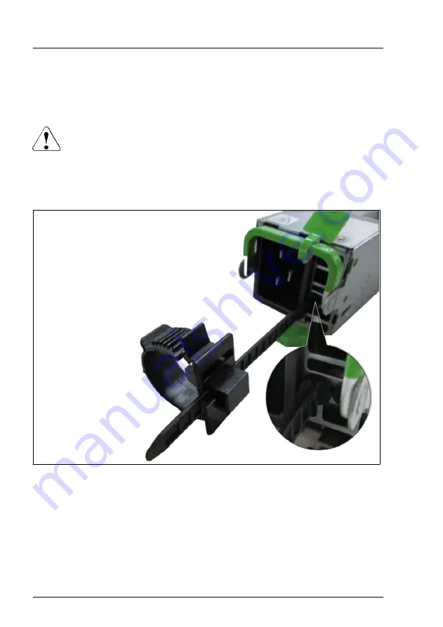
Figure 59: Inserting the cable clamp

Insert the cable clamp into the hole of the PSU as shown.

Connect the power cords to the PSUs.

Basic hardware procedures

84

Upgrade and Maintenance Manual

CX400 M6

Содержание PRIMERGY CX400 M6

Страница 1: ...FUJITSU Server PRIMERGY CX400 M6 Server Enclosure Upgrade and Maintenance Manual Upgrade and Maintenance Manual English 06 2021 ...

Страница 2: ...tas de Copyright and Trademarks Copyright 2021 FUJITSU LIMITED All rights reserved Delivery subject to availability right of technical modifications reserved All hardware and software names used are trademarks of their respective manufacturers The contents of this manual may be revised without prior notice Fujitsu assumes no liability for damages to third party copyrights or other rights arising f...

Страница 3: ...tic capacitors used in the printed circuit board assemblies of the product and in the mouse and keyboard are limited life components Use of these components beyond their operating life may result in electrolyte leakage or depletion potentially causing emission of foul odor or smoke As a guideline in a normal office environment 25 C operating life is not expected to be reached within the maintenanc...

Страница 4: ... ensuring the level of safety demanded of such use Please consult the sales staff of Fujitsu if intending to use this product for high safety use Measures against momentary voltage drop This product may be affected by a momentary voltage drop in the power supply caused by lightning To prevent a momentary voltage drop the use of an uninterruptible power supply is recommended This notice follows the...

Страница 5: ...pe of HDD used For more information on the usage and operation conditions of each available type of HDD see the following internet address https jp fujitsu com platform server primergy harddisk Only for Japan Shielded LAN cables should be used in this product UK Importer information Fujitsu Services Limited 22 Baker Street London W1U 3BW United Kingdom CX400 M6 Upgrade and Maintenance Manual ...

Страница 6: ...Version history Issue number Issue date Description V 1 0 11 2020 Early release V 2 0 06 2021 General release Upgrade and Maintenance Manual CX400 M6 ...

Страница 7: ...ent of unit categories 16 2 2 2 Customer Replaceable Units CRU 17 2 2 3 Upgrade and Repair Units URU 17 2 2 4 Field Replaceable Units FRU 18 2 3 Average task duration 19 2 4 Tools you need at hand 20 2 5 Documentation overview 21 2 5 1 About availability of manuals 21 2 5 2 List of documents 21 2 5 3 Further documents 23 3 Important information 25 3 1 Introduction 25 3 2 Safety instructions 25 3 2...

Страница 8: ...hardware procedures 39 4 1 Using diagnostic information 39 4 1 1 Proceeding 39 4 1 2 Locating the defective server 39 4 1 3 Determining the error class 40 4 1 4 Locating the defective component 40 4 2 Shutting down the server 41 4 3 Disconnecting the power cord 42 4 4 Removing server nodes from the server enclosure 43 4 5 Removing the server node dummy module 45 4 6 Installing or removing the fron...

Страница 9: ...procedures 87 5 1 Starting the maintenance task 87 5 1 1 Switching on the ID indicator 87 5 2 Completing the maintenance task 88 5 2 1 Verifying system information backup or restore 88 5 2 2 Performing a RAID array rebuild 89 5 2 3 Switching off the ID indicator 90 5 2 4 Viewing and clearing the System Event Log SEL 91 5 2 5 Performing a fan test 94 5 2 6 Updating Server View RAID Manager 95 5 2 7...

Страница 10: ...ackplane 119 7 7 Installing or removing the HDD SSD bridge board 130 7 8 Replacing the HDD SSD bridge board 135 7 9 Changing HDD SSD cage bezels 139 8 Fans 145 8 1 Safety notes 145 8 2 Basic information 145 8 3 Replacing a fan module 146 9 High speed riser module 149 9 1 Safety notes 149 9 2 Basic information 149 9 3 Replacing a high speed riser module 150 10 Power distribution board 155 10 1 Safe...

Страница 11: ... right front panel module 170 11 3 Front panel cable 177 11 3 1 Replacing the left front panel cable 177 11 3 2 Replacing the right front panel cable 181 11 4 Thermal cable 186 11 4 1 Removing the thermal cable 186 11 4 2 Installing the thermal cable 189 12 Cabling 193 12 1 Safety notes 193 12 2 Cabling information 193 13 Appendix A 195 13 1 Mechanical overview 195 13 1 1 Server enclosure front 19...

Страница 12: ...icators on hot plug HDD SSD PCIe SSD modules 201 13 2 2 Server enclosure rear 202 13 2 2 1 Indicator on hot plug PSU 202 13 2 2 2 Fan indicators 203 13 2 2 3 Indicators of the server nodes 204 13 3 Minimum startup configuration 204 14 Appendix B 207 14 1 Supplied documents 207 Content Upgrade and Maintenance Manual CX400 M6 ...

Страница 13: ...ssignment following remote diagnostics procedures as described in the ServerView Suite Local Service Concept LSC manual see Documentation overview on page 21 CAUTION The document at hand comprises procedures of a wide range of complexity Check the profile of qualification for technicians before assigning tasks Before you start carefully read Classification of procedures on page 16 1 2 Notational c...

Страница 14: ... with this symbol Failure to observe this warning may endanger your life destroy the system or lead to the loss of data Indicates additional information notes and tips Indicates the procedure category in terms of complexity and qualification requirements see Classification of procedures on page 16 Indicates the average task duration see Average task duration on page 19 Introduction 14 Upgrade and ...

Страница 15: ... tools are available see Tools you need at hand on page 20 2 1 2 Advanced Thermal Design ATD The ATD option allows you to operate the system with a wider temperature range either of 5 C to 40 C depending on your system and configuration This option can only be ordered from the manufacturer and is indicated by the respective logo on the identification rating plate CAUTION In a system that is config...

Страница 16: ...ator of your server available online at the following address https www fujitsu com fts products computing servers primergy index html For Japan https www fujitsu com jp products computing servers primergy Please contact your local Fujitsu customer service partner for details on how to order expansion kits or spare parts 2 2 Classification of procedures 2 2 1 Assignment of unit categories The comp...

Страница 17: ...ry For Japan https www fujitsu com jp products computing servers primergy support repair html Hot plug components increase system availability and guarantee a high degree of data integrity and fail safe performance Procedures can be carried out without shutting down the server or going offline Components that are handled as Customer Replaceable Units Hot plug HDD SSD modules Hot plug PSUs Peripher...

Страница 18: ...epair procedures involve shutting down and opening the server CAUTION The device may be seriously damaged or cause damage if it is opened without authorization or if repairs are attempted by unauthorized and untrained personnel Components that are handled as Upgrade Units None CAUTION Installing procedures involving Upgrade and Repair Units must be performed exclusively by Fujitsu service personne...

Страница 19: ...nufacturer from all liability Components that are handled as Field Replaceable Units HDD SSD backplane HDD SSD bridge board Fan module High speed riser module Power distribution board Front panel Front panel cable Thermal cable Please ask your local Fujitsu service center for more information 2 3 Average task duration Hardware 10 minutes The average task duration including preliminary and concludi...

Страница 20: ...nce procedures including preliminary and concluding software tasks Transport no Returning the server to its installation site where required depends on local customer conditions Assembly rack installation yes Reassembling the server installing the server in the rack if applicable Starting up no Booting time depends on hardware and software configuration and may vary significantly Table 1 Calculati...

Страница 21: ...ist of documents Document Description Safety Notes and Regulations manual 安全上のご注意 for Japan Important safety information available online or as a printed copy FUJITSU Server PRIMERGY CX400 M6 Server Enclosure Operating Manual Information how to install set up and operate your server enclosure available online FUJITSU Server PRIMERGY CX400 M6 Server Enclosure Upgrade and Maintenance Manual Instruct...

Страница 22: ...user guide Infrastructure Manager documentation FUJITSU Software Infrastructure Manager V2 6 0 Infrastructure Manager for PRIMEFLEX V2 6 0 User s Guide ServerView documentation ServerView Suite Local Service Concept LSC user guide ServerView Operations Manager Server Management user guide ServerView embedded Lifecycle Management eLCM user guide Illustrated Spares catalog Spare parts identification...

Страница 23: ...PU Intel VROC User Guide available online at https support ts fujitsu com For Japan https www fujitsu com jp products computing servers primergy manual Third party documentation Operating system documentation online help Peripherals documentation Table 2 List of documents 2 5 3 Further documents Document Description FUJITSU Server PRIMERGY CX2550 M6 CX2560 M6 Server Node Operating Manual Informati...

Страница 24: ...or FUJITSU Server PRIMERGY CX2550 M6 CX2560 M6 Server Node Reference Manual Information on configurable BIOS options and parameters available online Table 3 List of documents for the server nodes Before you start 24 Upgrade and Maintenance Manual CX400 M6 ...

Страница 25: ...nstructions are also provided in the manual Safety Notes and Regulations or 安全上のご注意 This server enclosure meets the relevant safety regulations for IT equipment If you have any questions about whether you can install the server enclosure in the intended environment please contact your sales outlet or our customer service team The actions described in this manual shall be performed by technical spe...

Страница 26: ...solutely dry before starting it up Material damage may be caused to the server enclosure if this requirement is not observed Only transport the server enclosure in its original packaging or in packaging that protects it from impacts and jolts In Japan and APAC transporting the server enclosure in its original packaging does not apply 3 2 3 Installation and operation This server enclosure should no...

Страница 27: ...peripheral device e g memory subsystem fails during a power outage The adequately shielded data cables must be used All data and signal cables must have sufficient shielding The use of cable type S FTP Cat5 or higher is recommended Use of unshielded or badly shielded cables may lead to increased emission of interference and or reduced fault tolerance of the device Ethernet cabling has to comply wi...

Страница 28: ...components marked with a warning notice e g lightning symbol may only be opened removed or exchanged by authorized qualified personnel Exception CSS components can be replaced The warranty is void if the server enclosure is damaged during installation or replacement of server enclosure expansions Only set screen resolutions and refresh rates that are specified in the operating manual for the monit...

Страница 29: ...ge depending on a configuration of option 3 2 4 Batteries Incorrect replacement of batteries may lead to a risk of explosion The batteries may only be replaced with identical batteries or with a type recommended by the manufacturer Do not throw batteries into the trash can Batteries must be disposed of in accordance with local regulations concerning special waste Ensure that you insert the battery...

Страница 30: ...cal properties of a CD DVD BD and cause imbalance and vibrations Damaged and imbalanced CDs DVDs BDs can break at high drive speeds data loss Under certain circumstances sharp CD DVD BD fragments can pierce the cover of the ODD equipment damage and can fly out of the drive danger of injury particularly to uncovered body parts such as the face or neck High humidity and airborne dust levels are to b...

Страница 31: ...h stickers or similar to the label side Doing so may cause rotational eccentricity and abnormal vibrations When a CD DVD BD is moved from a cold place to a warm place moisture condensation on the CD DVD BD surface can cause data read errors In this case wipe the CD DVD BD with a soft dry cloth then let it air dry Do not dry the CD DVD BD using devices such as a hair dryer To avoid dust damage and ...

Страница 32: ... be different When you handle ESD modules you must always observe the following points Switch off the server enclosure and remove the power plugs from the power outlets before installing or removing ESD modules The circuit boards and soldered parts of internal options are exposed and can be damaged by static electricity To ensure reliable protection you must wear an earthing band on your wrist whe...

Страница 33: ...rds EN 61340 5 1 ANSI ESD S20 20 3 2 8 Transporting the server enclosure CAUTION Only transport the server enclosure in its original packaging or in packaging that protects it from impacts and jolts In Japan and APAC transporting the server enclosure in its original packaging does not apply Do not unpack the server enclosure until it is at its installation location If you need to lift or transport...

Страница 34: ...ended from the rack there is a risk that the rack could tip over See the safety information of the rack and the warning label If the server enclosure rack is intended for permanent connection to the mains only an authorized specialist electrician is allowed to work Please follow the regulation of each country If the server enclosure is integrated into an installation that draws power from an indus...

Страница 35: ...Either the Performance Monitor or the Task Manager can be used to read out CPU utilization levels 3 4 CE conformity The system complies with the requirements of European Regulations Find the CE declaration on certificate portal https sp ts fujitsu com sites certificates default aspx CAUTION This is a Class A product In a domestic environment this product may cause RF interference In this case the ...

Страница 36: ...quipment does cause harmful interference to radio or television reception which can be determined by turning the equipment off and on the user is encouraged to try to correct the interference by one or more of the following measures Reorient or relocate the receiving antenna Increase the separation between equipment and the receiver Connect the equipment into an outlet on a circuit different from ...

Страница 37: ...well as during long breaks and after completion of work Packaging information This packaging information does not apply in Japan and APAC Do not throw away the packaging You may need it later for transporting the server enclosure If possible the equipment should only be transported in its original packaging Information on handling consumables Please dispose of printer consumables and batteries in ...

Страница 38: ...irective 2012 19 EU on waste electrical and electronic equipment WEEE This directive sets the framework for returning and recycling used equipment and is valid across the EU When returning your used device please use the return and collection systems available to you More information can be found at https ts fujitsu com recycling Details regarding the return and recycling of devices and consumable...

Страница 39: ...your local Fujitsu customer service partner for details on the service concept and on how to order expansion kits or spare parts 4 1 2 Locating the defective server Use the ID indicator for easy identification of the server especially when working in a datacenter environment or a server room Press the ID button on the front panel use the iRMC S5 web interface the ServerView Operations Manager or I...

Страница 40: ...ts that may be resolved by operating personnel The Global Error indicator and the CSS indicator can be found on the front side and the rear side of the server In some cases the indicator on the rear is designed as a combined indicator Global Error ID and CSS indicator The indicators also light up in standby mode and after a server restart due to a power failure Check the Global Error indicator and...

Страница 41: ...ep is only required when upgrading or replacing non hot plug components Inform the system administrator that the server will be shut down and put offline Terminate all applications Perform the required procedures described in the preliminary steps of each upgrade or maintenance task Shut down the server If the system is running an ACPI compliant operating system OS pressing the On Off button will ...

Страница 42: ...necting the power cord Before disconnecting the power cord all server nodes must be shut down Figure 2 Removing the cable clamp from the power cord Unlock the cable clamp 1 and remove the cable clamp from the power cord 2 Disconnect the power cord from the PSU 3 Basic hardware procedures 42 Upgrade and Maintenance Manual CX400 M6 ...

Страница 43: ...he meantime all remaining server nodes run in throttling mode with reduced performance Removing the CX2550 M6 or CX2560 M6 server node CAUTION Follow the safety instructions in Important information on page 25 Shut down the server node and disconnect all external cables Figure 3 Removing the CX2550 M6 or CX2560 M6 server node A Unlock the lever tip 1 Basic hardware procedures CX400 M6 Upgrade and ...

Страница 44: ...4 Removing the CX2550 M6 or CX2560 M6 server node B Open the lever 1 When the lever is fully open pull out the server node with the handle 2 Basic hardware procedures 44 Upgrade and Maintenance Manual CX400 M6 ...

Страница 45: ...led out 4 5 Removing the server node dummy module The CX400 M6 system must always run with closed node bays It is only allowed to leave a bay open for a limited time in case of repairing a server node for example In the meantime all remaining server nodes run in throttling mode with reduced performance CAUTION Follow the safety instructions in Important information on page 25 Basic hardware proced...

Страница 46: ...ism 1 of the release lever and pull the server node dummy module out of the bay 2 4 6 Installing or removing the front bezel Installing the brackets Figure 7 Front bezel overview 1 Left and right bracket Basic hardware procedures 46 Upgrade and Maintenance Manual CX400 M6 ...

Страница 47: ...bracket should only be done if the front bezel is installed for the first time Installing the front bezel Figure 9 Installing the front bezel brackets Insert the hook of the front cover into the hole of the right bracket 1 Press the latch on the left side of the front cover 2 Insert the front cover into the bracket on the left side 3 Basic hardware procedures CX400 M6 Upgrade and Maintenance Manua...

Страница 48: ...e front bezel If the key is locked release it 1 The front bezel is also available without a key cylinder In this case the key cylinder hole is capped Press the latch on the left side of the front cover 2 Then while pressing the latch pull the left side of the front bezel slightly forward 3 Remove the front bezel by sliding it to the left 4 Basic hardware procedures 48 Upgrade and Maintenance Manua...

Страница 49: ...he anti tilt plate to prevent the rack from tipping when installing the rack Pulling the server enclosure out of the rack without having installed the anti tilt plate may cause the rack to tip over Be careful not to pinch fingers or clothes when sliding out the server enclosure or pushing it back Failure to do so may cause injury For more information see Important information on page 25 If applica...

Страница 50: ...Do not use the extended server enclosure as a surface on which to put things or as a work surface and strictly avoid leaning on or against it 4 7 3 Removing the server enclosure from the rack In most cases maintenance tasks can be performed while the server enclosure is extended from the rack However depending on accessibility or security guidelines it may make sense to completely remove the serve...

Страница 51: ...erver enclosure out of the rack cabinet For configurations above 55 kg At least four people are needed to lift the server enclosure out of the rack cabinet Additionally a lifter is required in the following cases The server enclosure weighs more than 50 kg The server enclosure weighs more than 21 kg and is to be removed above the height of 25 U When using a lifter this removal procedure needs to b...

Страница 52: ...sure out of the rack as far as it will go 1 Release the locking springs on both rack rails 2 When using a cable management arm Figure 13 Removing the server enclosure from the rack A Pull the server enclosure out of the rack as far as it will go 1 Basic hardware procedures 52 Upgrade and Maintenance Manual CX400 M6 ...

Страница 53: ...llowing steps Release the locking springs on both sides of the rack rail by pressing the shift bracket 1 Remove the springs that are locking the rack rails on both sides 2 Figure 15 Removing the server enclosure from the rack B Basic hardware procedures CX400 M6 Upgrade and Maintenance Manual 53 ...

Страница 54: ...ving the top covers Removing the fan cover Figure 16 Removing the fan cover from the chassis Shift the locking tabs on both sides in the direction of the arrow 1 Fold up the fan cover 2 and remove it 3 The recessed grips for opening the cover are marked by green touch points Basic hardware procedures 54 Upgrade and Maintenance Manual CX400 M6 ...

Страница 55: ...assis Make sure that the fan cover is removed see Removing the fan cover on page 54 Remove two screws from the middle top cover see circles Push the middle top cover in the direction of the arrow 1 and remove it 2 Basic hardware procedures CX400 M6 Upgrade and Maintenance Manual 55 ...

Страница 56: ...ons regulations regarding electromagnetic compatibility and to prevent fires For more information see Important information on page 25 4 8 1 Installing the top covers Installing the middle top cover Figure 18 Installing the middle top cover on the chassis A Place the middle top cover on the chassis as shown 1 and slide it in the direction of the arrow 2 Basic hardware procedures 56 Upgrade and Mai...

Страница 57: ...Figure 19 Installing the middle top cover on the chassis B Fasten the middle top cover with the two original screws 6 32 see circles Basic hardware procedures CX400 M6 Upgrade and Maintenance Manual 57 ...

Страница 58: ...irection of the arrows 2 and flip down the cover 3 Shift the locking tab in the opposite direction of the arrow 2 to secure the fan cover CAUTION If the locking tab is stopped on the way to securing the fan cover shift the locking tab by finger into the locking position Basic hardware procedures 58 Upgrade and Maintenance Manual CX400 M6 ...

Страница 59: ...ving the inner rail from the rack rails Figure 21 Inner and outer rail Identify the inner 2 rail and the outer rail 1 Figure 22 Starting position of inner and outer rail Basic hardware procedures CX400 M6 Upgrade and Maintenance Manual 59 ...

Страница 60: ... inner rail as far as possible towards the front side 2 Figure 23 Turning outer rail Turn the rails to the other side Figure 24 Removing inner rail from outer rail Basic hardware procedures 60 Upgrade and Maintenance Manual CX400 M6 ...

Страница 61: ...m the outer rail Attaching the rack rails to the server enclosure Identify the right and the left rail Figure 25 Passing the latch Pass the latch at the end of the rack rail through the hole on the front of the chassis 1 Figure 26 Attaching the right rack rail Basic hardware procedures CX400 M6 Upgrade and Maintenance Manual 61 ...

Страница 62: ...ith two M4 screws see circles Repeat this procedure to install the left rack rail Installing the rack rails Clarify the position of the system unit in the rack Mark the position of the bottom edge of the server enclosure on the support uprights Identify the right and the left rail Basic hardware procedures 62 Upgrade and Maintenance Manual CX400 M6 ...

Страница 63: ...ase the positioning clip 1 after the designated position is reached Move the left rail towards the front side 4 while holding the positioning clip 3 The mounting aid must lock in the corresponding hole Figure 29 Adjusting the positioning clip Release the positioning clip 1 after the designated position is reached Basic hardware procedures CX400 M6 Upgrade and Maintenance Manual 63 ...

Страница 64: ...ghten the M5 screw on the rear side of the rail see circles 4 8 3 Installing the server enclosure in the rack CAUTION At least two people are needed to position the server enclosure on the rack rails For Japan see 安全上のご注意 Basic hardware procedures 64 Upgrade and Maintenance Manual CX400 M6 ...

Страница 65: ...ove 55 kg At least four people are needed to lift the server enclosure into the rack cabinet Additionally a lifter is required in the following cases The server enclosure weighs more than 50 kg The server enclosure weighs more than 21 kg and is to be installed above the height of 25 U When using a lifter this installation procedure needs to be carried out by maintenance personnel Basic hardware pr...

Страница 66: ... It is also ok to use other screws that are supplied to the shift bracket in order to attach the shift bracket Required tool For the stud Hexagon screw driver SW7 flat head screw driver For the other screws Phillips PH2 No 2 screw driver This only applies if the target chassis is not using the CMA Basic hardware procedures 66 Upgrade and Maintenance Manual CX400 M6 ...

Страница 67: ...ng the server enclosure into the rack A Slide the server enclosure into the rack until it is locked by the latch Figure 33 Removing the shift bracket Basic hardware procedures CX400 M6 Upgrade and Maintenance Manual 67 ...

Страница 68: ... using the CMA When using the CMA do not remove the shift bracket 4 8 4 Sliding the server enclosure into the rack When not using a CMA Figure 34 Mounting the server enclosure into the rack B Push the server enclosure into the rack When the server enclosure is stopped push the locking latch 1 on both sides and push the server enclosure into the rack again 2 Basic hardware procedures 68 Upgrade and...

Страница 69: ... When the server enclosure stops push the locking latch 1 on both sides and push the server enclosure into the rack 2 When the server enclosure does stop again push the shift brackets 3 on both sides and push the server enclosure into the rack 4 Basic hardware procedures CX400 M6 Upgrade and Maintenance Manual 69 ...

Страница 70: ...ing mechanism engages If the chassis was originally secured with screws re secure the chassis with screws 2 4 8 5 Installing the cable management arm CMA Parts of the CMA Figure 37 CMA parts 1 Right side CMA 2 Left side CMA 3 CMA stopper Basic hardware procedures 70 Upgrade and Maintenance Manual CX400 M6 ...

Страница 71: ...ft side of the CMA You can distinguish the sides by the engraving on the upper left part Figure 39 CMA Accompanying items A 1 Left side shift bracket 2 Right side shift bracket 3 Spacer 4 Screw RMK Basic hardware procedures CX400 M6 Upgrade and Maintenance Manual 71 ...

Страница 72: ...t RMK 2 Velcro tape RMK points at the accompanying items of the rack mounting kit Figure 41 CMA bracket position left and right side 1 Cage nut 2 Screw 3 Shift bracket 4 Spacer Basic hardware procedures 72 Upgrade and Maintenance Manual CX400 M6 ...

Страница 73: ...front side of the rack with the screws Figure 42 Connection points for the right side of the CMA 1 Connected to the outer side connector of the CMA 2 Not used this time 3 Connected to the inner side connector of the CMA 4 Inner rail of the RMK Basic hardware procedures CX400 M6 Upgrade and Maintenance Manual 73 ...

Страница 74: ...ht side CMA Install the CMA to the rear side of the RMK There are two latches for each side of the CMA One latch is for the inner side and one latch is for the outer side Figure 44 Installing the left side of the CMA The left side of the CMA is installed in the same way Basic hardware procedures 74 Upgrade and Maintenance Manual CX400 M6 ...

Страница 75: ...n store the cables from the lower slot in the CMA Figure 46 Routing the cables Open the CMA completely and press the cables to the base of the CMA 1 Fix the cables one by one with clamps at four positions from the inner side while arranging them and attach the cables to the CMA so that they don t stand out Also ensure that the cable is not excessively bent 2 Basic hardware procedures CX400 M6 Upgr...

Страница 76: ... Also ensure that the clamp is fixed as close to the PSU as possible Figure 48 State of the PSU cable when it is stored in the CMA on the right 1 Indicates two PSU cables 2 Indicates a single PSU cable Bend the PSU cable and secure it with velcro tape to prevent interference with the CMA Basic hardware procedures 76 Upgrade and Maintenance Manual CX400 M6 ...

Страница 77: ...ix the PSU cable just like the other cables to the CMA R or and the CMA L Figure 50 Installing the CMA stopper Install the CMA stopper to the rear side of the RMK see circles Basic hardware procedures CX400 M6 Upgrade and Maintenance Manual 77 ...

Страница 78: ...he RMK Figure 52 Note on routing the PSU cable If the PSU cable interferes with the CMA the cables secured to the CMA or the CMA stopper adjust the securing of the PSU cable to eliminate the interference Basic hardware procedures 78 Upgrade and Maintenance Manual CX400 M6 ...

Страница 79: ... are formed Figure 53 Note on cable condition Ensure that the cables are properly aligned and don t hang down Figure 54 Fixing the cables with a velcro tape Basic hardware procedures CX400 M6 Upgrade and Maintenance Manual 79 ...

Страница 80: ...odule CAUTION Follow the safety instructions in Important information on page 25 Figure 55 Installing the server node dummy module Carefully push the server node dummy module at the handle into the server enclosure until the locking mechanism snaps into place Basic hardware procedures 80 Upgrade and Maintenance Manual CX400 M6 ...

Страница 81: ...ay 3 4 Server node bay 4 5 PSU 1 6 PSU 2 Population rules for server nodes CX2550 M6 CX2560 M6 Number of nodes Bay 1 Bay 2 Bay 3 Bay 4 1 1 2 1 2 3 1 3 2 4 1 3 2 4 Table 4 CX2550 M6 CX2560 M6 population rules Not used bays must be equipped with server node dummy modules Mixing of the CX2550 M6 and CX2560 M6 server nodes is not supported Basic hardware procedures CX400 M6 Upgrade and Maintenance Man...

Страница 82: ...instructions in Important information on page 25 Figure 57 Pushing the server node into the server enclosure A Push the server node into the chassis while holding the handle 1 and use the lever to engage it 2 Basic hardware procedures 82 Upgrade and Maintenance Manual CX400 M6 ...

Страница 83: ...ure front on page 195 Stick the label that describes the product name and the serial number of the server node on the ID card The label that describes the product name and serial number is included in the delivery pack of the server node Before sticking the label write the server node bay number of the server node location on the label If you don t stick the label on the ID card you may not be abl...

Страница 84: ...e from 100 V 127 V or 200 V 240 V You may only operate the server enclosure if its rated voltage range corresponds to the local mains voltage Figure 59 Inserting the cable clamp Insert the cable clamp into the hole of the PSU as shown Connect the power cords to the PSUs Basic hardware procedures 84 Upgrade and Maintenance Manual CX400 M6 ...

Страница 85: ... will still continue to run Ensure that the status indicator on the PSU is lit green see Indicator on hot plug PSU on page 202 Figure 60 Example Locking the cable clamp of a PSU Attach a cable clamp to the power cord and tighten it as tight as possible 1 Secure the cable clamp as close to the PSU as possible 2 It will take about 60 seconds until the server enclosure can be powered on Basic hardwar...

Страница 86: ...xternal cables to the server node Figure 61 Controls and indicators of the server node 1 ID indicator 2 On Off button Power on indicator Press the On Off button either on the rear or on the corresponding front panel to start up the server node The power on indicator does lit green For more information see Node related indicators on page 199 Basic hardware procedures 86 Upgrade and Maintenance Manu...

Страница 87: ...the ID button on the front panel Press the ID button on the front panel to switch on the system identification LEDs For more information see Indicators on the front panel on page 198 Using the ID icon in the iRMC S5 web interface Log in to the iRMC S5 web interface The icon that represents the ID indicator LED resides on the right of the menu bar Its color symbolizes its status blue the ID LED is ...

Страница 88: ...estored from the system board to the new power distribution board automatically In order to verify whether the restore process has been successful check the System Event Log SEL see Viewing and clearing the System Event Log SEL on page 91 When using the Infrastructure Manager please refer to the following manuals about backup and restore function of system information See manual FUJITSU Software I...

Страница 89: ...is logged see Using the Chassis ID Prom Tool on page 96 to restore system information Automatic restore of chassis FRU data from backup file failed 5 2 2 Performing a RAID array rebuild After replacing an HDD that has been combined into a RAID array RAID rebuild will be performed completely unattended as a background process Ensure that the RAID array rebuild has started normally Wait until the pr...

Страница 90: ...tching off the ID indicator Press the ID button on the front panel or use the iRMC S5 web interface or ServerView Operations Manager to switch off the ID indicator after the maintenance task has been concluded successfully For more information see Locating the defective server on page 39 or the ServerView Suite Local Service Concept LSC and iRMC user guides Using the ID button on the front panel P...

Страница 91: ...the ID indicator from the Infrastructure Manager select a node from the Node List screen and operate ID LED from the Action button 5 2 4 Viewing and clearing the System Event Log SEL You can view the System Event Log SEL using the ServerView Operations Manager the iRMC S5 web interface or the Infrastructure Manager You can clear the System Event Log SEL using the iRMC S5 web interface You can coll...

Страница 92: ...er beforehand The status of the component will then be reset to ok To see the new status you must refresh the Driver Monitor view with Refresh For more information on how to view and sort the SEL using ServerView Operations Manager see the ServerView Operations Manager Server Management user guide Viewing the SEL using the iRMC S5 web interface Log in to the iRMC S5 web interface Open the Logs men...

Страница 93: ...reen from the Infrastructure Manager select a node from the Node List screen and click on the Display SEL link Clearing the SEL using the iRMC S5 web interface Log in to the iRMC S5 web interface Open the Logs menu Click System Event Log to open the System Event Log page All events concerning the system are displayed in a table in the Event Log Content group Click the Clear Logs button above the t...

Страница 94: ...eplacing a defective system fan or PSU containing a defective fan the fan error indicators will stay lit until the next fan test By default a fan test is automatically started every 24 hours The first automatic fan test being performed after replacing a fan will turn off the fan error indicator If you want to start the fan test manually you can do so by following the description below Executing th...

Страница 95: ...Click Save Page The fan test will be started at the specified time After the fan test is complete restore the time setting to its initial value and click Save Page In case of maintenance done by Fujitsu engineers in Japan Executing the fan test via Chassis ID Prom Tool Please follow the instructions provided separately 5 2 6 Updating Server View RAID Manager For the spare parts of the product comp...

Страница 96: ...urther instructions are available to maintenance personnel from the Fujitsu Technology Solutions Extranet https partners ts fujitsu com com service ps Servers PRIMERGY Select your PRIMERGY system from the main area of the page From the categories selection choose Software Tools Documentation In the Tools area click Tools Chassis IDProm Tool to download the file tool chassis Idprom Tool zip For Jap...

Страница 97: ...rop it by mistake injuries may result For more information see Important information on page 25 6 2 Basic information The server enclosure has two bays for hot plug PSUs The server enclosure is equipped with two hot plug PSUs that adjust automatically to any mains voltage in the range of 100 VAC to 240 VAC If one PSU is defective system can continue to work but it goes to a throttling mode if powe...

Страница 98: ...ass 2 within a server enclosure is not supported Mixing of Platinum PSUs within same class and different manufacturer e g class 1 within a server enclosure is supported Always install a dummy cover into an unused PSU bay to comply with applicable EMC regulations and satisfy cooling requirements For a redundant power supply configuration you need always two PSUs with the same power class Power supp...

Страница 99: ... down at work by revitalization Preliminary steps Locating the defective server on page 39 Check which PSU is defective A PSU is defective when the PSU status indicator lights orange For more information see Indicator on hot plug PSU on page 202 Only when replacing a PSU in a non redundant configuration Shutting down the server on page 41 Remove the power cord from the defective PSU see Disconnect...

Страница 100: ...wnward in the direction of the arrow 1 Press in on the green locking latch 2 While keeping the green locking latch pressed pull the PSU out of its bay 3 CAUTION Excessive temperatures could damage system components Never leave the bay for the hot plug PSU empty for more than two minutes during operation Power supply unit PSU 100 Upgrade and Maintenance Manual CX400 M6 ...

Страница 101: ...hot plug PSU Figure 66 Inserting the cable clamp The PSU does not have a cable clamp at first use Insert the cable clamp into the hole of the PSU as shown Power supply unit PSU CX400 M6 Upgrade and Maintenance Manual 101 ...

Страница 102: ...talling the hot plug PSU Carefully push the hot plug PSU into the empty bay until it stops 1 Ensure that the latch prevents the hot plug PSU from coming out Push the handle of the hot plug PSU as far as it will go in the direction of the arrow 2 Power supply unit PSU 102 Upgrade and Maintenance Manual CX400 M6 ...

Страница 103: ... the power cord on page 84 Only when replacing a PSU in a non redundant configuration Switching on the server nodes on page 86 Performing a fan test on page 94 6 4 Removing installing the PSU dummy module Customer Replaceable Unit CRU Hardware 5 minutes Tools tool less CAUTION Excessive temperatures could damage system components Never leave the bay for the hot plug PSU empty for more than two min...

Страница 104: ...dummy module Figure 69 Removing the PSU dummy module Press in on both release latches 1 and remove the PSU dummy module in the direction of the arrows 2 Power supply unit PSU 104 Upgrade and Maintenance Manual CX400 M6 ...

Страница 105: ...Installing the PSU dummy module Figure 70 Installing the PSU dummy module Insert the PSU dummy module in the empty bay until it stops Power supply unit PSU CX400 M6 Upgrade and Maintenance Manual 105 ...

Страница 106: ...Power supply unit PSU 106 Upgrade and Maintenance Manual CX400 M6 ...

Страница 107: ...DDs If a power failure should occur while the write cache is enabled cached data may be lost When disposing of transferring or returning an HDD or SSD wipe out the data on the drive for your own security Rough handling of HDDs may damage the stored data To cope with any unexpected problems always back up important data When backing up data to another HDD you should make backups on a file or partit...

Страница 108: ...control SAS HDDs SSDs an additional SAS RAID controller must be installed Hybrid configurations of SAS HDDs SATA HDDs SAS SSDs and SATA SSDs within the same logical drive RAID array are not supported If the server node has the corresponding RAID configuration HDD SSD modules can also be replaced during operation HDD SSD bays assignment Up to six HDDs SSDs are installed in a cage The cages are assi...

Страница 109: ...r view 0 1 2 3 4 5 0 1 2 3 4 5 0 1 2 3 4 5 0 1 2 3 4 5 Node 1 Node 2 Node 3 Node 4 Table 8 HDD SSD cages and front panel front view HDD SSD backplane types There are three different HDD SSD backplanes Figure 71 HDD backplane 1 1 2x HDDs Hard disk drive HDD solid state disk SSD CX400 M6 Upgrade and Maintenance Manual 109 ...

Страница 110: ...2 3 and two SAS SATA PCIe SSD combi connectors 4 5 This backplane is used with CX2560 M6 server nodes HDD backplane 1 3 A3C40233555 provides 6 PCIe SSD connectors 0 1 2 3 4 5 This backplane is used with CX2560 M6 server nodes This backplane needs the bridge board A3C40233554 The following figures show how the cages depending of the installed backplanes can be equipped Hard disk drive HDD solid sta...

Страница 111: ...DD backplane 1 2 0 3 SAS SATA 4 5 SAS SATA PCIe SSD Figure 75 Configuration with type C HDD backplane 1 3 0 5 PCIe SSD HDD SSD cage bezels There are two different bezels to cover unused HDD SSD cages or unused HDD SSD respectively Hard disk drive HDD solid state disk SSD CX400 M6 Upgrade and Maintenance Manual 111 ...

Страница 112: ...SSD 4x front bezel only for CX2550 M6 Instead four HDD SSD dummy modules can also be installed 7 3 Installing 2 5 inch HDD SSD modules Customer Replaceable Unit CRU Hardware 5 minutes Tools Preliminary and concluding steps tool less Main steps tool less Hard disk drive HDD solid state disk SSD 112 Upgrade and Maintenance Manual CX400 M6 ...

Страница 113: ... dummy module Figure 78 Removing a 2 5 inch HDD SSD dummy module Press both tabs together 1 and pull the dummy module out of its bay 2 CAUTION Keep the dummy module for future use Always replace dummy modules into unused HDD SSD bays to comply with applicable EMC regulations and satisfy cooling requirements Hard disk drive HDD solid state disk SSD CX400 M6 Upgrade and Maintenance Manual 113 ...

Страница 114: ...1 and open the locking lever 2 Figure 80 Installing the 2 5 inch HDD SSD module Insert the HDD SSD module into a drive bay and carefully push back as far as it will go 1 Close the locking lever to lock the HDD in place 2 Hard disk drive HDD solid state disk SSD 114 Upgrade and Maintenance Manual CX400 M6 ...

Страница 115: ...install the front bezel see Installing the front bezel on page 47 7 4 Removing 2 5 inch HDD SSD modules Customer Replaceable Unit CRU Hardware 5 minutes Tools tool less Preliminary steps If applicable remove the front bezel see Removing the front bezel on page 48 If the HDD SSD module to be removed is combined into a RAID array please proceed as follows Hard disk drive HDD solid state disk SSD CX4...

Страница 116: ...er you first need to delete the array using ServerView RAID Manager CAUTION All data on all HDDs SSDs in the array will be lost when deleting the RAID array Be sure to back up your data before deleting a RAID array For more information see the ServerView Suite RAID Management user guide Removing a 2 5 inch HDD SSD module Pinch the green locking clips and open the locking lever see Figure 79 Pull t...

Страница 117: ...o the unused HDD SSD bay to comply with applicable EMC regulations and satisfy cooling requirements Figure 81 Installing the 2 5 inch dummy module Push the dummy module into the empty bay until it engages Concluding steps If applicable install the front bezel see Installing the front bezel on page 47 Hard disk drive HDD solid state disk SSD CX400 M6 Upgrade and Maintenance Manual 117 ...

Страница 118: ... RAID levels 0 1 10 5 and 50 are supported for internal HDD configurations Modular RAID 5 6 controller with MegaRAID functionality MegaRAID RAID levels 0 1 10 5 50 6 and 60 are supported for internal HDD configurations As an option a flash backup unit FBU can save the memory content even if the power fails Cache memory size of up to 8 GB is available An HDD SSD module can be replaced while the sys...

Страница 119: ...D SSD modules on page 112 Concluding steps If applicable install the front bezel see Installing the front bezel on page 47 If the HDD SSD is configured using a RAID controller with a RAID level higher than 0 the rebuild will start automatically see Performing a RAID array rebuild on page 89 Updating Server View RAID Manager on page 95 7 6 Replacing a 2 5 inch HDD SSD backplane Field Replaceable Un...

Страница 120: ... If applicable remove relevant 2 5 inch HDD SSD dummy module see Removing a 2 5 inch HDD SSD dummy module on page 113 Extending the server enclosure out of the rack on page 49 Removing the top covers on page 54 Removing the defective high speed riser module on page 151 Remove the fan modules see Removing the fan module on page 147 Removing the fan cage The following steps are required before the s...

Страница 121: ...Figure 83 Disconnecting the PDB B Pull the cable out of the chassis as shown Figure 84 Removing the fan cage Hard disk drive HDD solid state disk SSD CX400 M6 Upgrade and Maintenance Manual 121 ...

Страница 122: ...rs 4 Removing the 2 5 inch HDD backplane Figure 85 Disconnecting the cable from the backplane Disconnect the cable from the connector on the backplane side of the cable 1 Disconnect the other end of the cable from the connector on the bridge board side 2 This should only be done if the bridge board or the cable itself needs to be replaced Hard disk drive HDD solid state disk SSD 122 Upgrade and Ma...

Страница 123: ...86 Removing the 2 5 inch HDD backplane Carefully pull up on the backplane in a vertical motion and remove it from its slot 1 Hard disk drive HDD solid state disk SSD CX400 M6 Upgrade and Maintenance Manual 123 ...

Страница 124: ... inch HDD backplane Align the backplane module with the pins on both sides of the connectors of the backplane see circle Insert the backplane into the connector on the bridge board 1 Hard disk drive HDD solid state disk SSD 124 Upgrade and Maintenance Manual CX400 M6 ...

Страница 125: ...n the bridge board side of the cable 1 However if the cable is already connected this operation does not need to be performed Connect the other end of the cable to the connector on the backplane side 2 Hard disk drive HDD solid state disk SSD CX400 M6 Upgrade and Maintenance Manual 125 ...

Страница 126: ...er Insert the backplane holder as shown 1 and place it on the backplane module 2 Align the two holes on the backplane holder with the protrusions on the top of the backplane module Hard disk drive HDD solid state disk SSD 126 Upgrade and Maintenance Manual CX400 M6 ...

Страница 127: ... cage Carefully insert the fan cage in the chassis Figure 91 Fastening the fan cage Fasten the fan cage with two screws on each side see circle Hard disk drive HDD solid state disk SSD CX400 M6 Upgrade and Maintenance Manual 127 ...

Страница 128: ...n cage so that the edge of the fan cage does not leap over from the edge of the chassis Figure 93 Fastening the fan cage Fasten the fan cage with four screws on the backplane holders see circles Hard disk drive HDD solid state disk SSD 128 Upgrade and Maintenance Manual CX400 M6 ...

Страница 129: ...nect each cable to the PDB Also fasten the cables with a clamp see circles Figure 95 Placing the cables Place the cables in the space on each side of the fan cage Hard disk drive HDD solid state disk SSD CX400 M6 Upgrade and Maintenance Manual 129 ...

Страница 130: ...a 2 5 inch dummy module on page 117 If applicable install the front bezel see Installing the front bezel on page 47 If the server node was originally installed in server node bay 2 and or 4 install it see Installing server nodes in the server enclosure on page 81 Connecting the power cord on page 84 Switching on the server nodes on page 86 7 7 Installing or removing the HDD SSD bridge board Upgrad...

Страница 131: ...relevant HDD SSD cage see Removing a 2 5 inch HDD SSD module on page 116 If applicable remove all 2 5 inch HDD SSD dummy module see Removing a 2 5 inch HDD SSD dummy module on page 113 Removing server nodes from the server enclosure on page 43 Removing the defective hot plug PSU on page 100 Extending the server enclosure out of the rack on page 49 Removing the top covers on page 54 Removing the de...

Страница 132: ...gure 96 Removing the HDD SSD bridge board Remove the two hexagonal spacers 1 Remove the air duct 2 Remove the screws securing the HDD SSD bridge board 3 Hard disk drive HDD solid state disk SSD 132 Upgrade and Maintenance Manual CX400 M6 ...

Страница 133: ...Figure 97 Removing the HDD SSD bridge board Carefully lift up the HDD SSD bridge board in the direction of the arrow Hard disk drive HDD solid state disk SSD CX400 M6 Upgrade and Maintenance Manual 133 ...

Страница 134: ...rd and secure it with a hexagonal spacer 3 Secure the HDD SSD bridge board with a hexagonal spacer 4 Concluding steps Installing the power distribution board kit on page 161 Install all HDD backplanes see Installing the 2 5 inch HDD backplane on page 124 Installing the fan cage on page 126 Install all fan modules see Installing the fan module on page 148 Installing the new high speed riser module ...

Страница 135: ... new hot plug PSU on page 101 Connecting the power cord on page 84 Switching on the server nodes on page 86 7 8 Replacing the HDD SSD bridge board Field Replaceable Unit FRU Hardware 40 minutes Tools Preliminary and concluding steps Phillips PH2 No 2 hexagonal cross SW5 PZ2 Main steps tool less Preliminary steps Shut down the server nodes see Shutting down the server on page 41 Disconnecting the p...

Страница 136: ...oving the top covers on page 54 Removing the defective high speed riser module on page 151 Remove all fan modules see Removing the fan module on page 147 Removing the fan cage on page 120 Remove all HDD backplanes see Removing the 2 5 inch HDD backplane on page 122 Removing the power distribution board kit on page 157 Removing the HDD SSD bridge board Figure 99 Installing the HDD SSD bridge board ...

Страница 137: ...2 Remove the screws securing the HDD SSD bridge board 3 Figure 100 Removing the HDD SSD bridge board Carefully lift up the HDD SSD bridge board in the direction of the arrow Hard disk drive HDD solid state disk SSD CX400 M6 Upgrade and Maintenance Manual 137 ...

Страница 138: ...rd and secure it with a hexagonal spacer 3 Secure the HDD SSD bridge board with a hexagonal spacer 4 Concluding steps Install all HDD backplanes see Installing the 2 5 inch HDD backplane on page 124 Installing the power distribution board kit on page 161 Installing the fan cage on page 126 Install all fan modules see Installing the fan module on page 148 Installing the new high speed riser module ...

Страница 139: ...e on page 81 Connecting the power cord on page 84 Switching on the server nodes on page 86 7 9 Changing HDD SSD cage bezels Customer Replaceable Unit CRU Hardware 5 minutes Tools Preliminary and concluding steps tool less Main steps Phillips PH2 No 2 hexagonal cross SW5 PZ2 Preliminary steps If applicable shut down the relevant server node see Shutting down the server on page 41 Disconnecting the ...

Страница 140: ... enclosure out of the rack on page 49 Removing the HDD SSD x6 front bezel Figure 102 Removing the front bezel fixing screw Remove the corresponding screw from the top of the chassis see circle Figure 103 Removing the HDD SSD x6 front bezel screw type Hard disk drive HDD solid state disk SSD 140 Upgrade and Maintenance Manual CX400 M6 ...

Страница 141: ...SSD x4 front bezel Figure 104 Removing the front bezel fixing screw Remove the corresponding screw from the top of the chassis see circle Figure 105 Removing the HDD SSD x4 front bezel Grasp behind the bezel and remove it from the cage Hard disk drive HDD solid state disk SSD CX400 M6 Upgrade and Maintenance Manual 141 ...

Страница 142: ...it into the cage Figure 107 Installing the front bezel B Secure the corresponding front bezel with one screw from top of the chassis see circle Installing the HDD SSD x4 front bezel If applicable remove the HDD SSD modules beside the front bezel see Removing 2 5 inch HDD SSD modules on page 115 Hard disk drive HDD solid state disk SSD 142 Upgrade and Maintenance Manual CX400 M6 ...

Страница 143: ... empty cage and rotate it as shown by the arrows to snap it into the cage Figure 109 Installing the front bezel B Secure the corresponding front bezel with one screw from top of the chassis see circle Hard disk drive HDD solid state disk SSD CX400 M6 Upgrade and Maintenance Manual 143 ...

Страница 144: ... cage see Installing a 2 5 inch dummy module on page 117 Sliding the server enclosure into the rack on page 68 If applicable install the front bezel see Installing the front bezel on page 47 Connecting the power cord on page 84 If applicable switch on the relevant server node see Switching on the server nodes on page 86 Hard disk drive HDD solid state disk SSD 144 Upgrade and Maintenance Manual CX...

Страница 145: ...g a grounded object before handling electrostatic sensitive devices ESDs Do not touch the circuitry on boards or soldered parts Hold circuit boards by their metallic areas or edges If devices are installed or disassembled using methods other than those outlined in this chapter the warranty will be invalidated The procedure of installation on this notes might change depending on a configuration of ...

Страница 146: ...y and concluding steps Phillips PH2 No 2 hexagonal cross SW5 PZ2 Main steps tool less Preliminary steps If applicable remove the front bezel see Removing the front bezel on page 48 Extending the server enclosure out of the rack on page 49 Removing the fan cover on page 54 Fans 146 Upgrade and Maintenance Manual CX400 M6 ...

Страница 147: ...tors on page 203 Removing the fan module Figure 111 Removing the fan module Pinch the handles 1 on both sides to release the lock and lift it up 2 CAUTION The fan blade rotates by inertia Don t touch the fan blade after the fan module was removed from the chassis Fans CX400 M6 Upgrade and Maintenance Manual 147 ...

Страница 148: ...s down firmly until it is fully seated in the bay Concluding steps Installing the fan cover on page 58 Sliding the server enclosure into the rack on page 68 If applicable install the front bezel see Installing the front bezel on page 47 Performing a fan test on page 94 Fans 148 Upgrade and Maintenance Manual CX400 M6 ...

Страница 149: ...s discharge static build up e g by touching a grounded object before handling electrostatic sensitive devices ESDs Do not touch the circuitry on boards or soldered parts Hold circuit boards by their metallic areas or edges If devices are installed or disassembled using methods other than those outlined in this chapter the warranty will be invalidated For more information see Important information ...

Страница 150: ... page 41 Disconnecting the power cord on page 42 If applicable remove the server nodes from the server enclosure see Removing server nodes from the server enclosure on page 43 If applicable remove the front bezel see Removing the front bezel on page 48 Extending the server enclosure out of the rack on page 49 Removing the top covers on page 54 Locating the defective component on page 40 High speed...

Страница 151: ...ve high speed riser module Figure 114 Loosening the high speed riser module Loosen the two screws see circles of the corresponding high speed riser module High speed riser module CX400 M6 Upgrade and Maintenance Manual 151 ...

Страница 152: ...ed riser module Unlock the lever tip and use the lever to remove the high speed riser module from the bridge board 1 Then lift the high speed riser module like that 2 High speed riser module 152 Upgrade and Maintenance Manual CX400 M6 ...

Страница 153: ...le between FAN1 and FAN2 and FAN4 and FAN 5 as shown Place the high speed riser module on the connector guide pin on the bridge board and the guide pin on the power distribution board Push the high speed riser module in the connectors without using the lever High speed riser module CX400 M6 Upgrade and Maintenance Manual 153 ...

Страница 154: ...server enclosure into the rack on page 68 If applicable install the front bezel see Installing the front bezel on page 47 If applicable install the server nodes in the server enclosure see Installing server nodes in the server enclosure on page 81 Connecting the power cord on page 84 Switching on the server nodes on page 86 High speed riser module 154 Upgrade and Maintenance Manual CX400 M6 ...

Страница 155: ...c build up e g by touching a grounded object before handling electrostatic sensitive devices ESDs Do not touch the circuitry on boards or soldered parts Hold circuit boards by their metallic areas or edges If devices are installed or disassembled using methods other than those outlined in this chapter the warranty will be invalidated The procedure of installation on this notes might change dependi...

Страница 156: ...ss Preliminary steps Shutting down the server on page 41 Disconnecting the power cord on page 42 Removing server nodes from the server enclosure on page 43 Removing the defective hot plug PSU on page 100 If applicable remove the front bezel see Removing the front bezel on page 48 Extending the server enclosure out of the rack on page 49 Removing the top covers on page 54 Power distribution board 1...

Страница 157: ...ng the fan cage on page 120 Removing the power distribution board kit Figure 119 Removing the screws Remove the two screws securing the air duct Remove the air duct Loosen the four screws on the power distribution board kit see circles Power distribution board CX400 M6 Upgrade and Maintenance Manual 157 ...

Страница 158: ... the arrow 1 Remove the power distribution board kit upward without colliding with the protrusions inside the chassis 2 Removing the power distribution board Figure 121 Loosening the power distribution board Remove the four screws see circles Power distribution board 158 Upgrade and Maintenance Manual CX400 M6 ...

Страница 159: ...on bolts and stand off pins see circles 10 4 Installing the power distribution board kit Field Replaceable Unit FRU Hardware 15 minutes Tools Preliminary and concluding steps Phillips PH2 No 2 hexagonal cross SW5 PZ2 Main steps tool less Power distribution board CX400 M6 Upgrade and Maintenance Manual 159 ...

Страница 160: ...two stand off pins see circles Place the power distribution board on the installation bolts and stand off pins Figure 124 Fastening the power distribution board Fasten the power distribution board with four screws on the power distribution board holder see circles Power distribution board 160 Upgrade and Maintenance Manual CX400 M6 ...

Страница 161: ...of the arrow with avoiding the emboss of the chassis 1 Align both connectors on the power distribution board kit with the connector on the bridge board and the cutout of the power distribution board holder with the T guide pin of the chassis Push down the power distribution board kit until it locks in place 2 Power distribution board CX400 M6 Upgrade and Maintenance Manual 161 ...

Страница 162: ... 126 Installing the fan module on page 148 Installing the new high speed riser module on page 153 Installing the top covers on page 56 Sliding the server enclosure into the rack on page 68 If applicable install the front bezel see Installing the front bezel on page 47 Installing the new hot plug PSU on page 101 Installing server nodes in the server enclosure on page 81 Power distribution board 162...

Страница 163: ...on page 41 Disconnecting the power cord on page 42 Removing server nodes from the server enclosure on page 43 Removing the defective hot plug PSU on page 100 If applicable remove the front bezel see Removing the front bezel on page 48 Extending the server enclosure out of the rack on page 49 Removing the top covers on page 54 Removing the fan module on page 147 Removing the fan cage on page 120 Re...

Страница 164: ...iding the server enclosure into the rack on page 68 Installing the new hot plug PSU on page 101 Installing server nodes in the server enclosure on page 81 If applicable install the front bezel see Installing the front bezel on page 47 Connecting the power cord on page 84 Switching on the server nodes on page 86 Verifying system information backup or restore on page 88 Power distribution board 164 ...

Страница 165: ... ESDs Do not touch the circuitry on boards or soldered parts Hold circuit boards by their metallic areas or edges For more information see Important information on page 25 11 2 Front panel module 11 2 1 Replacing the left front panel module Field Replaceable Unit FRU Hardware 5 minutes Tools Preliminary and concluding steps tool less Main steps Phillips PH2 No 2 Preliminary steps Shutting down the...

Страница 166: ...on page 49 Removing the top covers on page 54 Removing the front panel Figure 127 Loosening the front panel A Pull the cable from the side of the fan cage Figure 128 Loosening the front panel B Front panel 166 Upgrade and Maintenance Manual CX400 M6 ...

Страница 167: ...he front panel by removing two screws see circles Figure 129 Disconnecting the front panel Disconnect the front panel cable from the front panel see circle Front panel CX400 M6 Upgrade and Maintenance Manual 167 ...

Страница 168: ...Installing the front panel Figure 130 Connecting the front panel Connect the front panel cable to the front panel see circle Front panel 168 Upgrade and Maintenance Manual CX400 M6 ...

Страница 169: ...Figure 131 Securing the front panel A Fasten the front panel with two screws see circles Front panel CX400 M6 Upgrade and Maintenance Manual 169 ...

Страница 170: ...Sliding the server enclosure into the rack on page 68 If applicable install the front bezel see Installing the front bezel on page 47 Connecting the power cord on page 84 Switching on the server nodes on page 86 11 2 2 Replacing the right front panel module Field Replaceable Unit FRU Hardware 5 minutes Front panel 170 Upgrade and Maintenance Manual CX400 M6 ...

Страница 171: ...wer cord on page 42 If applicable remove the front bezel see Removing the front bezel on page 48 Extending the server enclosure out of the rack on page 49 Removing the top covers on page 54 Removing the front panel Figure 133 Loosening the front panel A Pull the cable from the side of the fan cage Front panel CX400 M6 Upgrade and Maintenance Manual 171 ...

Страница 172: ...Figure 134 Loosening the front panel B Loosen the front panel by removing two screws see circles Front panel 172 Upgrade and Maintenance Manual CX400 M6 ...

Страница 173: ...Figure 135 Disconnecting the front panel Disconnect the front panel cable from the front panel see circle Front panel CX400 M6 Upgrade and Maintenance Manual 173 ...

Страница 174: ...Installing the front panel Figure 136 Connecting the front panel Connect the front panel cable to the front panel see circle Front panel 174 Upgrade and Maintenance Manual CX400 M6 ...

Страница 175: ...Figure 137 Securing the front panel A Secure the front panel with two screws see circles Front panel CX400 M6 Upgrade and Maintenance Manual 175 ...

Страница 176: ...ng steps Installing the top covers on page 56 Sliding the server enclosure into the rack on page 68 If applicable install the front bezel see Installing the front bezel on page 47 Connecting the power cord on page 84 Switching on the server nodes on page 86 Front panel 176 Upgrade and Maintenance Manual CX400 M6 ...

Страница 177: ...he left from the relevant HDD SSD cage see Removing a 2 5 inch HDD SSD module on page 116 If applicable remove the 2 5 inch HDD SSD dummy modules until slot 6 from the left from the relevant HDD SSD cage see Removing a 2 5 inch HDD SSD dummy module on page 113 Extending the server enclosure out of the rack on page 49 If applicable remove the front bezel mounted on the left end see Removing the HDD...

Страница 178: ...e 166 Figure 139 Removing the left front panel cable A Disconnect the cable from the PDB and remove the cable from the clamp see circles Figure 140 Removing the left front panel cable B Carefully pull the front panel cable out of the cable duct Front panel 178 Upgrade and Maintenance Manual CX400 M6 ...

Страница 179: ...he front panel cable through the cable duct Ensure to connect the labeled side of the cable to the power distribution board 1 Figure 142 Installing the left front panel cable B Connect the cable to the PDB Also fasten the cable with a clamp see circles Front panel CX400 M6 Upgrade and Maintenance Manual 179 ...

Страница 180: ...erver enclosure into the rack on page 68 If applicable install the HDD SSD modules until slot 6 from the left into the relevant HDD SSD cage see Installing a 2 5 inch HDD SSD module on page 114 If applicable install the 2 5 inch HDD SSD dummy modules until slot 6 from the left into the relevant HDD SSD cage see Installing a 2 5 inch dummy module on page 117 If applicable install the front bezel se...

Страница 181: ...ee Removing a 2 5 inch HDD SSD module on page 116 If applicable remove the 2 5 inch HDD SSD dummy modules until slot 6 from the right from the relevant HDD SSD cage see Removing a 2 5 inch HDD SSD dummy module on page 113 Extending the server enclosure out of the rack on page 49 If applicable remove the front bezel mounted on the right end see Removing the HDD SSD x6 front bezel on page 140 If app...

Страница 182: ...ront panel cable A Disconnect the cable from the PDB see circle Figure 145 Removing the right front panel cable B Pull out the system ID card unlock it 1 and then pull it out 2 Front panel 182 Upgrade and Maintenance Manual CX400 M6 ...

Страница 183: ...cable duct Installing the right front panel cable Figure 147 Installing the right front panel cable A Carefully shift the front panel cable through the cable duct Ensure to connect the labeled side of the cable to the power distribution board 1 Front panel CX400 M6 Upgrade and Maintenance Manual 183 ...

Страница 184: ...able properly as shown Figure 149 Installing the right front panel cable B Insert the system ID card into the chassis Insert the system ID card into the chassis Ensure to not damage the right front panel cable when inserting the system ID card Front panel 184 Upgrade and Maintenance Manual CX400 M6 ...

Страница 185: ...hown Concluding steps Installing the top covers on page 56 If applicable install the front bezel mounted on the right end see Installing the HDD SSD x6 front bezel on page 142 If applicable install the front bezel mounted on the right end see Installing the HDD SSD x4 front bezel on page 142 Sliding the server enclosure into the rack on page 68 Front panel CX400 M6 Upgrade and Maintenance Manual 1...

Страница 186: ...des on page 86 11 4 Thermal cable 11 4 1 Removing the thermal cable Field Replaceable Unit FRU Hardware 15 minutes Tools Preliminary and concluding steps tool less Main steps Phillips PH2 No 2 Preliminary steps Shutting down the server on page 41 Disconnecting the power cord on page 42 If the server node is installed in server node bay 2 remove it see Removing server nodes from the server enclosur...

Страница 187: ...oving the HDD SSD x6 front bezel on page 140 If applicable remove the front bezel mounted on the left end see Removing the HDD SSD x4 front bezel on page 141 Removing the top covers on page 54 Remove the left high speed riser module see Removing the defective high speed riser module on page 151 Removing the thermal cable Figure 152 Removing the thermal cable A Disconnect the cable from the PDB and...

Страница 188: ...e from the side of the HDD cage along with the rubber bushing 1 Remove the rubber bushing from the thermal cable 2 Figure 154 Removing the thermal cable C Carefully pull the thermal cable out of the cable duct Front panel 188 Upgrade and Maintenance Manual CX400 M6 ...

Страница 189: ...ing steps tool less Main steps Phillips PH2 No 2 Installing the thermal cable Figure 155 Installing the thermal cable A Carefully shift the thermal cable through the cable duct Ensure to connect the labeled side of the cable to the power distribution board 1 Front panel CX400 M6 Upgrade and Maintenance Manual 189 ...

Страница 190: ... to the thermal cable 1 Insert the thermal cable with the rubber bushing into the HDD cage 2 Figure 157 Installing the thermal cable C Connect the cable to the PDB Also fasten the cable with a clamp see circles Front panel 190 Upgrade and Maintenance Manual CX400 M6 ...

Страница 191: ...erver enclosure into the rack on page 68 If applicable install the HDD SSD modules until slot 6 from the left into the relevant HDD SSD cage see Installing a 2 5 inch HDD SSD module on page 114 If applicable install all 2 5 inch HDD SSD dummy modules until slot 6 from the left into the relevant HDD SSD cage see Installing a 2 5 inch dummy module on page 117 If applicable install the front bezel se...

Страница 192: ...Front panel 192 Upgrade and Maintenance Manual CX400 M6 ...

Страница 193: ...on the cable to disconnect cables Ensure that none of the cables are scraped strained or otherwise damaged while replacing system components Immediately replace cables with damaged shielding Always use shielded network cables 12 2 Cabling information Figure 159 Cabling CX400 M6 Upgrade and Maintenance Manual 193 ...

Страница 194: ...40233582 HDD SSD backplane signal cable 2 A3C40233583 HDD SSD backplane power cable 3 A3C40233577 Front panel cable L R 4 A3C40233581 Thermal cable Table 9 List of used cables Cabling 194 Upgrade and Maintenance Manual CX400 M6 ...

Страница 195: ...server nodes 1 Front panel for server node 2 2 Front panel for server node 4 3 Front panel for server node 3 4 ID card 5 HDD bays for server node 4 6 HDD bays for server node 3 7 HDD bays for server node 2 8 HDD bays for server node 1 9 Front panel for server node 1 Front overview with CX2560 M6 server nodes Using CX2560 M6 server nodes the server enclosure can be equipped with up to 24x 2 5 inch ...

Страница 196: ...ddresses and DNS name for Japan only the product name and the serial number can be found on the ID card Also the notation ID card is displayed on the front of the system ID card 13 1 2 Server enclosure rear Rear overview with CX2550 M6 or CX2560 M6 server nodes Figure 162 Configuration with CX2550 M6 or CX2560 M6 server nodes 1 Installation bay 1 for server nodes 2 Installation bay 2 for server no...

Страница 197: ...2 4x CX2550 M6 or 4x CX2560 M6 3 Power Distribution Board 4 5x fan modules 5 HDD SSD bridge board under fan cage 6 4x HDD SSD cages each with up to 6 HDD SSD bays not visible 7 2x High speed riser not visible 8 2x front panel not visible Appendix A CX400 M6 Upgrade and Maintenance Manual 197 ...

Страница 198: ...ndicator 2 FAN CSS indicator 3 Global Error indicator 4 ID indicator 5 Power on indicator 6 CSS indicator Enclosure related indicators PSU CSS indicator 1 Status Description off No critical event detected CSS component orange on Prefailure event detected CSS component flashing orange CSS component failure detected Appendix A 198 Upgrade and Maintenance Manual CX400 M6 ...

Страница 199: ...is used as an example Global Error indicator 3 See also iRMC related status signals on page 201 Status Description off No critical event detected non CSS component orange on Prefailure event detected non CSS component flashing orange Non CSS component failure detected Possible causes System is out of the specified temperature range Defective sensor CPU error Error detected by server management sof...

Страница 200: ...erver is switched off green on The server node has been switched on but Power Cycle Delay settings delay it from turning on for a specified time The server node is switched on and operating normally white flashing slowly 1 2 Hz The iRMC firmware is starting up after the server node has been connected to the mains CSS indicator 6 Status Description off No critical event detected CSS component orang...

Страница 201: ... progress For more information on the emergency flash of the iRMC firmware see the FUJITSU Server PRIMERGY CX2550 M6 CX2560 M6 Server Node Upgrade and Maintenance Manual 13 2 1 2 Indicators on hot plug HDD SSD PCIe SSD modules Figure 165 Indicators on an HDD SSD PCIe SSD module 1 Access indicator 2 Error indicator Access indicator 1 Status Description off The HDD SSD is inactive green on The HDD S...

Страница 202: ...ess has failed The HDD SSD module has not been inserted correctly flashing orange slowly HDD SSD RAID rebuild is in progress Data is being restored after replacing a drive that has been combined into a RAID array 13 2 2 Server enclosure rear 13 2 2 1 Indicator on hot plug PSU Figure 166 Indicator on hot plug PSU 1 PSU status indicator Appendix A 202 Upgrade and Maintenance Manual CX400 M6 ...

Страница 203: ...e Warning has been detected The PSU is still running but failure might be imminent orange on A PSU failure has been detected Possible causes The power supply is failing The power supply is not receiving input power when AC is supplied to one power supply in a redundant configuration 13 2 2 2 Fan indicators Figure 167 Fan indicators 1 FAN indicator Appendix A CX400 M6 Upgrade and Maintenance Manual...

Страница 204: ... Field Replaceable Units FRU If the server does not start up or other problems occur it may be necessary to take the system down to its most basic configuration in order to isolate the defective component The minimum startup configuration consists of the following components and cables Component Notes 1 Server node CX2550 M6 or CX2560 M6 1 PSU Table 10 Minimum startup configuration components Cabl...

Страница 205: ... nodes on page 86 CAUTION Since the fan module is not included in the minimum startup configuration the server must be shut down immediately after the diagnostic process is complete POST phase has been passed The minimum startup configuration must be used exclusively for diagnostic purposes by maintenance personnel never in daily operation Appendix A CX400 M6 Upgrade and Maintenance Manual 205 ...

Страница 206: ...Appendix A 206 Upgrade and Maintenance Manual CX400 M6 ...

Страница 207: ...pendix B 14 1 Supplied documents The following documents are available in this appendix Screw list for FUJITSU Server PRIMERGY CX2550 M6 CX2560 M6 Reference Manual CX400 M6 Upgrade and Maintenance Manual 207 ...

Страница 208: ...EAR BRACKET HDD SSD x6 FRONT BEZEL HDD SSD x4 FRONT BEZEL 6 32 Phillips PH2 No 2 hexagonal cross SW5 POWER DISTRIBUTION BOARD AIR DUCT PDB BRIDGE BOARD M3 x 5 5 mm Phillips PH2 No 2 CMA shift bracket M5 x 12 mm Hexagon screw driver SW7 CMA shift bracket M5 x 12 mm Phillips PH2 No 2 CHASSIS Front M5 ...

Страница 209: ...PH2 No 2 RMK Rear M5 Phillips PH2 No 2 RMK Inner rail M4 Hexagon screw driver SW10 BRIDGE BOARD AIR DUCT BRIDGE BOARD 6 32 Phillips PH2 No 2 POWER DISTRIBUTION BOARD KIT M3 Phillips PH2 No 2 HIGH SPEED RISER M3 ...

Отзывы: