background image

20

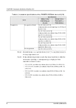
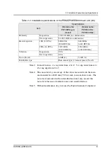
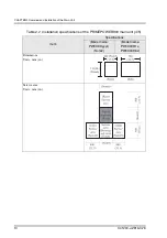
U41290-J-Z816-3-76

CHAPTER 3 Main Unit Power-on/off


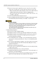
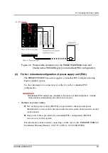
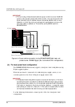
Figure 3.5  Power cable connection for the PRIMEPOWER900 main unit

(model name: PW0X0CR1x, PW0X0CR6x) 
(non-redundant PSU configuration)

(2)

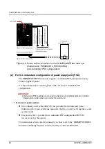
For N+1 redundant configuration of power supply unit (PSU)

The PRIMEPOWER900 main unit supports a redundant PSU configuration using 

Fujitsu-supplied options.

Use this information to connect power cables for an N+1 redundant PSU 

configuration:

4

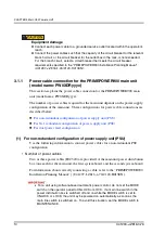
Redundant PSU options are mounted in the main unit before shipment.  Include 
these options when placing an order for a main unit.

• Number of power cables

l

Two or three power cables (IEC320) are provided for the main unit power 

distribution box (one each for the main unit, the first system board, and the second 

system board).

l

One power cable is provided for a redundant PSU configuration (IEC320)  

(an accessory for the option)

For information about correctly connecting a cable, refer to the “PRIMEPOWER900 

Installation Planning Manual” (U41297-J-Z816-x-76/C120-H013EN).

Содержание PRIMEPOWER900

Страница 1: ...Edition September 2004 PRIMEPOWER900 ...

Страница 2: ...included at the back of the manual There you will also find the addresses of the relevant User Documentation Department Copyright and Trademarks This manual is printed on paper treated with chlorine free bleach Copyright Fujitsu Siemens Computers GmbH 2003 2004 All rights reserved Delivery subject to availability right of technical modifications reserved All hardware and software names used are tr...

Страница 3: ...entally friendly materials that can be fully recycled Read on through the next sections for a brief look at some of the measures we have intro duced in an effort to protect the environment as well as our tips and suggestions for environ mentally friendly handling of your system Environmentally friendly product design and development This product has been designed in accordance with the Siemens sta...

Страница 4: ...t your local Fujitsu Siemens Computers branch office subsidiary Service If you have any complaints in relation to missing faulty parts please contact the complaints department of Fujitsu Siemens Computers Tel 49 0 5251 8 22222 Fax 49 0 5251 8 22029 You can also submit complaints via the internet http www fujitsu siemens com servers quality reklamation_us htm Email reklamation cs fujitsu siemens co...

Страница 5: ...rd applications such as office work personal device household appliance and general industrial applications This product is not intended for use in nuclear reactor control systems aeronautical and space systems air traffic control systems mass transportation control systems medical devices for life support missile launch control systems or other specialized uses in which extremely high levels of r...

Страница 6: ...ent has been tested and found to comply with the limits for a Class B digital divice pursuant to Part 15 of FCC Rules These limits are designed to provide reasonable protection against harmful interference in a residential installation This equipment generates uses and can radiate radio frequency energy and if not installed and used in accordance with instructions may cause harmful interference to...

Страница 7: ...nual may be revised without prior notice The contents of this manual shall not be disclosed in any way or reproduced in any media without the express written permission of Fujitsu Limited All Rights Reserved Copyright FUJITSU LIMITED 2003 2004 ...

Страница 8: ......

Страница 9: ... Fujitsu Siemens Computers adds the reference to the documentation belonging to the PRIMESTATION the standard hardware platform of SMCs at Fujitsu Siemens Computers adds a URL to request for additional host IDs and replaces the comment forms 02 2003 04 20 2003 07 14 Entire manual addition and correction F 3 addition Technical brush up Error corrections Addition of description for expanded interlea...

Страница 10: ...etion of description for the Fast Memory Mode Fujitsu Siemens Computers reprocesses the manual in the same way as for the first two manual versions except of the following two changes Dual Power Feed is no longer part ot the standard equipment of the systems supplied by Fujitsu Siemens Computers The respective changes made in the former manual versions were cancelled And besides the PRIMESTATION a...

Страница 11: ...ins l Structure and contents of this manual l Other reference manuals l Notations l Prompt Notations l Environmental requirements for using this product l Conventions for warning messages l For the readers Structure and Contents of this Manual This manual is organized as described below CHAPTER 1 Features Describes the features of the main unit CHAPTER 2 Overview and Installation of the Main Unit ...

Страница 12: ...ds Appendix C PCI Disk Box Outlines the PCI disk box and describes the names and functions of its components installation specifications and notes on installation Appendix D UPC Connector Specifications Describes UPC connector specifications Appendix E Notes Describes the points to be noted regarding the overall system configuration of the main unit Also describes the configuration for fast memory...

Страница 13: ...013EN c Online manual preinstalled in the internal disk of the System Management Console System Console Software User s Guide also available as U41258 J Z775 x 76 For how to refer to manuals in b and c above see Referring to Other Manuals on SMC in the PRIMEPOWER HPC2500 2500 1500 900 Installation Guide U41300 J Z816 x 76 C120 E162EN Text Conventions This manual uses the following fonts and symbol...

Страница 14: ...duct is a computer intended for use in an office environment For details on the operational environment see the PRIMEPOWER900 Installation Planning Manual U41297 J Z816 x 76 C120 H013EN Prompt Meaning Example RC2000 C shell prompt in RC2000 RC2000 command y n filename SMC C shell prompt in SMC SMC command y n filename Prompt Meaning Example RC2000 Bourne shell and Korn shell prompt in RC2000 RC200...

Страница 15: ...rm the procedure correctly This indicates a hazardous situation could result in minor or moderate personal injury if the user does not perform the procedure correctly This signal also indicates that damage to the product or other property may occur if the user does not perform the procedure correctly This indicates information that could help the user to use the product more effectively This indic...

Страница 16: ......

Страница 17: ...fore connecting any of the power cables of the main unit If all the power cables of the main unit are connected to a single power strip a serious current leakage exceeding the stipulated level may flow through the ground cable of the power strip Use a power strip with an industrial plug if the power strip is not directly connected to the distribution panel 6 Equipment damage l Connect each power c...

Страница 18: ... has several power cables To turn off all power to the main unit after the power switch has been turned off disconnect all of these power cables 49 Data destruction Do not forcibly turn off the power to a partition while the partition is running normally Doing so could cause the destruction of data 52 Equipment damage Be sure to follow the precautions below when installing the PCI disk box Otherwi...

Страница 19: ...6 3 76 ix NOTES ON SAFETY Alert Labels The following labels are attached to this product These labels provide information to the users of this product Main unit PRIMEPOWER900 PCI disk box Never peel off the labels ...

Страница 20: ......

Страница 21: ...gging or unplugging of external interface cables l Maintenance and inspections repairing and regular diagnosis and maintenance The following tasks regarding this product and the optional products provided from Fujitsu Fujitsu Siemens Computers should only be performed by a certified service engineer Users must not perform these tasks Incorrect operation of these tasks may cause malfunction l Unpac...

Страница 22: ......

Страница 23: ...Installation specifications 7 2 3 Connecting the SMC 11 CHAPTER 3 Main Unit Power on off 13 3 1 Connecting the Power Cables 13 3 1 1 Power cable connection for the PRIMEPOWER900 main unit model name PW0XDRyyyx 14 3 1 2 Power cable connection for the PRIMEPOWER900 main unit model name PW0X0CR1x PW0X0CR6x 19 3 2 Power on off the Main Unit 24 3 2 1 Power on 24 3 2 2 Power off 26 3 3 Power on off a Pa...

Страница 24: ...Operator Panel 47 5 1 1 Exterior view of the operator panel 48 5 1 2 Message display function 49 5 1 3 Mode switch 50 5 1 4 Forced termination of partition processing 52 5 2 Display Format of Operator Panel 53 5 3 Using the Operator Panel 56 5 3 1 Temperature indication symbol T 56 5 3 2 AC input status indication symbol Z 56 5 3 3 Abnormal status symbol 57 5 3 4 System operation symbol 0 58 CHAPT...

Страница 25: ...3 Backing up the system console software SCS setup data 90 8 2 4 Restoring the system console software setup data 90 Appendix A OBP Environment Variables 93 A 1 OBP Environment Variables configuration policy 93 A 2 Other OBP Environment Variables 94 Appendix B Adding hostids 99 Appendix C PCI Disk Box 101 C 1 Overview 101 C 2 PCI Disk Box Components and Functions 103 C 2 1 Front view 103 C 2 2 Rea...

Страница 26: ...of UPC Interface 123 Appendix E Notes 125 E 1 Notes on System Configuration 125 E 1 1 System control and operation environment 125 E 1 2 Connecting a UPS unit 127 E 1 3 On board LAN port 128 E 1 4 On board serial interface 129 E 1 5 Multiport console connection unit 129 E 2 Notes on Power Control 130 E 2 1 Power on from LAN 130 E 2 2 Characteristics of SMC 130 E 2 3 Facility control 130 E 2 4 Wait...

Страница 27: ...odel name PW0X0CR1x PW0X0CR6x dual power feed configuration 23 Figure 3 8 The operator panel mode switch 24 Figure 3 9 The operator panel power switch 25 Figure 4 1 PRIMEPOWER900 main unit front view 30 Figure 4 2 PRIMEPOWER900 main unit rear view 30 Figure 4 3 System Board 31 Figure 4 4 CPU module 32 Figure 4 5 Memory module 33 Figure 4 6 Basic I O board 34 Figure 4 7 Locations of basic I O board...

Страница 28: ...h a PCI disk box 115 Figure D 1 Connection with UPS 118 Figure D 2 Corresponding terminals in the UPC interface cable 120 Figure D 3 UPC connector 121 Figure D 4 6 port UPS interface connection box 122 Figure D 5 Signal cable connection between one UPS and one main unit 123 Figure D 6 Signal cable connection between two or more UPS units and one main unit 123 Figure D 7 Signal cable connection bet...

Страница 29: ...of operation menu symbols on operator panel 54 Table 5 3 Command list 55 Table 5 4 Correspondence between mode switch positions and partition operations 55 Table 6 1 Partition mode 62 Table 6 2 System board CPU and PCI numbers used in PPAR and XPAR modes 66 Table 7 1 Error messages displayed on the operator panel 77 Table A 1 Configuration policy values and degraded units 93 Table A 2 Console path...

Страница 30: ......

Страница 31: ...processor clock speed may result in higher power consumption and a higher heat release value l The main unit central processing unit is a SPARC64 V l CPU modules with different clock speeds can be mounted together in the same unit l Up to sixteen way interleaved memory subsystems depending on the SDRAM modules are used l Mounted 64 bit PCI slots can operate at 66 MHz l The system can be connected ...

Страница 32: ...ard the DR function is used In addition faulty CPUs and memory are hot swappable For replacement components must be disconnected and installed in units of system boards l Each partition is protected and errors are isolated to single partition helping to assure application reliability 1 3 Expanded Maintenance and Operational Functions The equipment maintenance feature of the main unit prevents occu...

Страница 33: ...s specifications of the main unit Table 2 1 Main unit specifications 1 2 Item Specifications Remarks Form Rack mount type System board Up to 8 CPUs 8 PCI slots Up to 2 boards mountable CPU Type SPARC64 V Number of CPUs Up to 16 CPUs One to eight CPUs per system board Main memory memory module Unit of expansion 2G bytes 4G bytes 8G bytes four modules per set Error checking and correction ECC Storag...

Страница 34: ...ive None shares the DAT drive of the SMC Standard I O interface LAN Note1 Up to two ports per system board 100Base TX 10Base T RS 232C Note2 Two ports per system board DSUB 25 pin See Appendix E SCSI For internal hard disk PCI slots 36 slots 8 slots for system boards x 2 10 slots for PCI disk boxes x 2 Redundant components Power supply unit fan tray power system dual power feed option and disk for...

Страница 35: ... from exceeding the maximum ambient temperature specified for the main unit The maximum allowable operating temperature of the main unit in the rack is 35 C 95 F l A certain amount of air flow is required for safe operation of the main unit mounted in the rack The main unit has ventilation openings at the front and rear Do not cover or close the ventilation openings Doing so may cause the main uni...

Страница 36: ... Use grounding that is Class 3 or higher To prevent malfunctioning of the main unit do not use a shared ground connection Always use an independent ground connection l Do not run any cable beneath any equipment Also prevent cables from becoming taut Never disconnect the power cable of the main unit while power is being supplied to the main unit l Keep objects off the top of the main unit l In wint...

Страница 37: ...r supply Voltage 200 to 240 VAC 10 single phase Frequency 50 60Hz 2 to 4 Power requirement 1 SB 8 CPUs 2500 VA 2000 VA 2 SBs 16 CPUs 4000 VA 3500 VA Power consumption 1 SB 8 CPUs 2450 W 1800 W 2 SBs 16 CPUs 3950 W 3150 W Maximum current consumption 1 SB 8 CPUs 12 5 A 6 25 A per power cable 2 power cables 10 0 A 5 A per power cable 2 power cables 2 SBs 16 CPUs 20 0 A 6 7 A per power cable 3 power c...

Страница 38: ...e2 In model names x is any letter from A to Z Y is any letter from A to Z or any digit from 0 to 9 Note3 If the ambient temperature exceeds the values listed below while the main unit is operating a warning message is displayed Take immediate corrective action 35 C 95 F installed at an altitude from 0 to 1500 m 0 to 4921 2 ft 33 C 91 4 F installed at an altitude from 1500 to 2000 m 4921 2 to 6561 ...

Страница 39: ...t type 16 mount spaces Note5 Note2 In model names x is any letter from A to Z Y is any letter from A to Z or any digit from 0 to 9 Note4 This noise level is an average of the values measured with the main unit mounted in a 1800 mm 70 9 in rack in an anechoic room The noise level measured with an installed main unit may exceed this noise level because of ambient noise and sound reflection Note5 Wit...

Страница 40: ...d Installation of the Main Unit Dimensions Units mm in Service area Units mm in Table 2 2 Installation specifications of the PRIMEPOWER900 main unit 4 5 Item Specifications Model name PW0XDRyyyx Note2 Model name PW0X0CR1x PW0X0CR6x 711 28 Note6 ...

Страница 41: ...ets Note8 This service area is required for removing the main unit from the rack for maintenance purposes Note9 This dimension depends on the rack in which the main unit is mounted Check the specifications of the rack to be used Note10 The side service area can be omitted if there is a passage or other space about 800 mm 31 5 in wide that can be used as the service area l the system administrator ...

Страница 42: ......

Страница 43: ... l Power on off the Main Unit l Power on off a Partition 3 1 Connecting the Power Cables The PRIMEPOWER900 main unit has no circuit breaker Therefore to turn on or off the main unit either connect or disconnect the main unit power cables Figure 3 1 Power distribution box used by Fujitsu Siemens Computers This section provides procedures and precautions for connecting the power cables ...

Страница 44: ...ain unit the first system board and the second system board For information about correctly connecting a cable refer to the PRIMEPOWER900 Installation Planning Manual U41297 J Z816 x 76 C120 H013EN 4 For a unit using software based automatic power control do not set the MODE switch on the operator panel to UNLOCK or LOCK If a main line switch in the power distribution box is switched off and on wh...

Страница 45: ... 1 redundant PSU configuration 4Redundant PSU options are mounted in the main unit before shipment Include these options when placing an order for a main unit Number of power cables l Two or three power cables IEC320 are provided for the main unit power distribution box one each for the main unit the first system board and the second system board l One power cable is provided for a redundant PSU c...

Страница 46: ...The PRIMEPOWER900 main unit supports a dual power feed configuration using Fujitsu supplied options When the main unit is connected to two different power supply sources it can continue operation even if one of the power supply sources fails 4A dual power feed configuration requires a dual power feed option If the main unit without the option mounted is connected to different power supply sources ...

Страница 47: ... power distribution box one each for the main unit the first system board and the second system board l Three power cables are provided for dual power feed configuration IEC320 accessories for the option For information about correctly connecting a cable refer to the PRIMEPOWER900 Installation Planning Manual U41297 J Z816 x 76 C120 H013 01EN ...

Страница 48: ...luded as standard equipment with the main unit primary power feed in the figure above An additional power distribution box must be purchased separately for secondary power feed Figure 3 4 Power cable connection for the PRIMEPOWER900 main unit model name PW0XDRyyyx dual power feed configuration Connected to the power distribution box for primary power feed Connected to the power distribution box fo...

Страница 49: ...wer supply unit PSU Use the following information to connect power cables for a non redundant PSU configuration Number of power cables l Two or three power cables IEC320 are provided for the main unit power distribution box one each for the main unit the first system board and the second system board l For information about correctly connecting a cable refer to the PRIMEPOWER900 Installation Plann...

Страница 50: ... an N 1 redundant PSU configuration 4Redundant PSU options are mounted in the main unit before shipment Include these options when placing an order for a main unit Number of power cables l Two or three power cables IEC320 are provided for the main unit power distribution box one each for the main unit the first system board and the second system board l One power cable is provided for a redundant ...

Страница 51: ... main line switch in the power distribution box is switched off and on while the MODE switch is set to UNLOCK or LOCK the unit may be powered on automatically as soon as the main line switch is switched on To avoid this set the MODE switch to MAINTENANCE Figure 3 6 Power cable connection for the PRIMEPOWER900 main unit model name PW0X0CR1x PW0X0CR6x N 1 redundant PSU configuration ...

Страница 52: ...figuration This option is mounted in the main unit before shipment Include this option when placing an order for a main unit If this option is required after the main unit has been installed in the field consult your sales representative Use the following information to connect power cables for a dual power feed configuration Number of power cables l Two or three power cables IEC320 are provided w...

Страница 53: ...e unit may be powered on automatically as soon as the main line switch is switched on To avoid this set the MODE switch to MAINTENANCE Note One power distribution box is included as standard equipment with the main unit primary power feed in the figure above An additional power distribution box must be purchased separately for secondary power feed Figure 3 7 Power cable connection for the PRIMEPOW...

Страница 54: ...b the SMC a Power on using the operator panel 1 Turn on the power switches of the SMC and peripheral units For information on how to power on the SMC see the manual supplied with the platform 2 Set the mode switch to the required mode Figure 3 8 The operator panel mode switch The operation of the main unit after the power on off varies depending on the state of the mode switch For information on p...

Страница 55: ...lied with the platform 2 Turn on the main unit by executing the System Power On Instruction in the Machine Administration Menu of the system console software For details on the power on process using the Machine Administration Menu see Section 6 2 System Power Operation in the System Console Software User s Guide 2 Automatic power on The power supply can be started automatically using the automati...

Страница 56: ... until the shutdown process finishes it may take a few minutes The message POWER OFF is displayed on the panel while the main unit is shutting down and after the shutdown of the partitions is completed 4 After the power off process is complete the message POWER ON READY appears Check this message and turn off the peripheral power switches For information on the power off conditions restricted by t...

Страница 57: ...see Section 6 5 Auto Power Control System APCS in the System Console Software User s Guide 3 3 Power on off a Partition This section describes how to turn on off a partition 3 3 1 Power on a Partition This section describes how to turn on partition You can manually power on a partition using either a the operator panel or b the SMC a Power on a partition using the operator panel 1 Confirm that the...

Страница 58: ...nd Shutdown of Partitions in the System Console Software User s Guide 3 3 2 Power off a partition To shutdown a partition enter the shutdown command from the remote console window of the respective partition For details on powering off partitions see Section 7 1 3 Shutdown of partitions in the System Console Software User s Guide ...

Страница 59: ...l System Control Facility l Power Supply Unit l Fan Tray l Air Filter l System Management Console SMC l Multiport Console Connection Unit 4 1 Device Configuration The basic component of the main unit is the System Board which mounts up to eight processors Two system boards can be mounted in the PRIMEPOWER900 main unit Figure 4 1 and Figure 4 2 show the front and rear views respectively of the PRIM...

Страница 60: ...30 U41290 J Z816 3 76 CHAPTER 4 Hardware Overview Figure 4 1 PRIMEPOWER900 main unit front view Figure 4 2 PRIMEPOWER900 main unit rear view ...

Страница 61: ...the specifications of the System Board 4 2 2 System board expansion One system board can be added in the PRIMEPOWER900 main unit Up to two system boards can be inserted into system board slots Up to eight CPU modules and up to thirty two memory modules can be mounted on a system board For system board expansion contact a certified service engineer Table 4 1 System board specifications Item Details...

Страница 62: ...4 V processor that conforms to the SPARC V9 architecture l One system board accommodates up to eight CPU modules l To improve the reliability of the system error checking and correction ECC is employed ECC is also used to check errors in the primary cache and secondary cache of the CPU For CPU module expansion contact a certified service engineer Figure 4 4 CPU module ...

Страница 63: ...ccess memory SDRAM l Memory modules employ error checking and correction ECC l Upgrades of memory modules must be done in sets of four All memory modules mounted on a system board must be of the same type For memory module expansion contact a certified service engineer Note The riser card is an adapter card that is used to efficiently mount memory modules onto the system board Figure 4 5 Memory mo...

Страница 64: ...unted on the right side of the unit These boards are not interchangeable l The basic I O board conforms to the PCI local bus specifications Rev 2 1 l The basic I O board supports a bus width of 64 bits and clock frequencies of 33 MHz 5 0 V and 33 66 MHz 3 3 V l The PCI slot supports hot replacement PCI Hot Plug For details refer to Section 4 5 3 PCI hot plug l Standard I O features on the basic I ...

Страница 65: ...s All PCI slots support either 64 bit or 32 bit PCI cards l PCI clock rate MHz This is the clock frequency of the relevant slot If a PCI card operable at both 33 MHz and 66 MHz is inserted into a PCI slot at 33 66 MHz the PCI card operates on a 66 MHz clock l Card input voltage This is the input voltage of the PCI bus of the relevant PCI slot A PCI card operable only at 3 3 VDC will not work when ...

Страница 66: ... the clock frequency of the relevant slot If a PCI card operable at both 33 MHz and 66 MHz is inserted into a PCI slot at 33 66 MHz the PCI card operates on a 66 MHz clock l Card input voltage This is the input voltage of the PCI bus of the relevant PCI slot A PCI card operable only at 3 3 VDC will not work when inserted into a 5 VDC PCI slot but will work in a 3 3 VDC PCI slot Table 4 3 Specifica...

Страница 67: ...t will work in a 5 VDC PCI slot A universal PCI card is operable at both 3 3 VDC and 5 VDC and is operable in all PCI slots l Size short Means a short sized PCI card long Means a long sized PCI card Note that a short sized PCI card can also be mounted in a long sized card slot Figure 4 7 Locations of basic I O boards and PCI slots ...

Страница 68: ...nt configuration The target adapter can be replaced without stopping the job Hot system expansion PCI cards can be added to handle an increase in jobs while the system is running 4 5 3 2 Insertion and extraction of PCI cards l For information about the workflow when the PCI hot plug is used and the procedure for replacement and expansion refer to the PCI Hot Plug User s Guide I O device edition l ...

Страница 69: ...ty board monitors and controls the PRIMEPOWER900 l System Control Facility board provides a LAN port for connection to the SMC This is a private LAN l The LAN can only be used to establish network connections with the SMC and the multiport console connection unit Figure 4 8 System Control Facility board ...

Страница 70: ... see Dual power feed option 1 Note 1 For information about the dual power feed configuration see Dual power feed option Figure 4 9 PSU expansion Table 4 4 lists the specifications of the Power Supply Unit Table 4 4 Specifications of the power supply unit Item Specification Input Voltage Rated voltage 100 to 240 VAC Phase Single Variation 10 to 10 Frequency Rated frequency 50 to 60 Hz Variation 3 H...

Страница 71: ...e power systems This option is mounted in the main unit Connecting AC power to the main unit form two separate power systems provides redundancy This allows the system to operate continuously even if a power failure occurs in one of the input power systems When planning the installation of a UPS note that a UPS needs to be installed for each power line ...

Страница 72: ...in unit Figure 4 10 Fan tray Operation of the fan tray is monitored inside the unit If one of the fans fails a message indicating the defective fan is displayed on the operator panel and the SMC For details on messages displayed when a defective fan is detected see the Section 7 4 Error Messages Displayed on the Operator Panel ...

Страница 73: ...air filter is installed in the front of the unit as a dust guard The efficiency of the cooling system may decrease if the filter is not cleaned on a reqular basis Filter preventive maintenance is part of the contracted server maintenance The main unit need not be stopped for air filter cleaning Cleaning should only be performed by a certified service engineer ...

Страница 74: ... Machine Administration Menu of the system console software on the SMC l Displaying a console screen for each partition l Automatic power control By configuring the main unit s power on off schedules the main unit can be turned on or off automatically l Time synchronization NTP Network Time Protocol server feature By using NTP the SMC synchronizes the time of each partition to the time in the SMC ...

Страница 75: ... system control LAN l The multiport console connection unit can display a console for each partition on a different window of the SMC l One RS232C cable is supplied with the unit l One 100VAC power cable is supplied with the multiport console connection unit A 200VAC power can be purchased separately l A multiport console connection unit occupies 1U of rack space Figure 4 11 Multiport console conn...

Страница 76: ......

Страница 77: ...on off l State indication LCD l Power on state indication POWER LED l Malfunction indication CHECK LED l Reset function partition specific l Request interleave function partition specific l Partition startup function partition specific The power on off reset interrupt and start up functions can be defined for each partition The operator panel is covered by the main unit s front cover Even the fron...

Страница 78: ...age then press the switch again Figure 5 1 Operator panel 1 State indication LCD The state indication LCD shows a message or symbol during operation 2 POWER LED green The POWER LED lights in green when the main unit power is turned on 3 CHECK LED amber The CHECK LED lights in amber if an error occurs in the main unit 4 Mode switch 3 position slide switch The mode switch which is on the operator pa...

Страница 79: ...te of power supply AC input fan and intake air temperature and humidity l State of each partition and error information for each component l Information about the device whose power supply is controlled by the main unit When any of the switches is pressed or the information that is displayed on the state indication LCD is modified the state indication LCD backlight goes on If the switches are not ...

Страница 80: ...tenance state This mode should be used only for maintenance by trained customer engineers The alive check of the operating system is disabled so no hang up in the operating system can be detected This mode enables sending the Break signal recognition MAINTENANCE In MAINTENANCE mode the system is placed in a hardware maintenance state This mode should only be used for maintenance by trained custome...

Страница 81: ...e operating system OS is running when a Poff operation described above is initiated the OS starts its shutdown sequence and the main unit power is turned off after shutdown Remote Pon Poff Note1 Pon Poff by the power switch Only power on is enabled auto boot Enabled boot stop Enabled boot stop Pon Poff by the SMC Enabled auto boot Enabled boot stop Enabled boot stop Pon Poff by the F7973RC1 Note2 ...

Страница 82: ...n dump switch instruction This instruction stops the running partition and collects a data dump After the dump is written to disk the partition is reset and the operating system is restarted Partition reset instruction This instruction resets the running partition Use this instruction only if the partition dump switch instruction is disabled or if any other error has occurred in the operating syst...

Страница 83: ...display area showing the operating status of the main unit or a menu of operations l Second line Symbols for operations that you specify using the cursor switch and decision switch as described below RR RCI segment ID decimal notation This ID is not used for this main unit NN Node ID hexadecimal notation If more than one main unit is connected to the RCI network this ID is assigned to identify eac...

Страница 84: ...ode switch For details see Table 5 4 Table 5 2 Meanings of operation menu symbols on operator panel Symbol Indication Explanation Remarks T Temperature Temperature of the air intake section of the main unit Z AC input status Status of the AC input section AC input status is displayed for each AC input source Abnormal status error An error occurred in the main unit This symbol is only displayed if ...

Страница 85: ...d partition and restarts Request REQ None displays execution confirmation message Request to acquire OS dump of the selected partition Acquires OS dump of selected partition enters OS panic state then automatically restarts partition Up UP None displays execution confirmation message Request to activate the selected partition Starts the selected partition Table 5 4 Correspondence between mode swit...

Страница 86: ...ay LCD To execute the operation use the decision switch 5 3 1 Temperature indication symbol T 1 Press the Cursor switch to move the underline cursor on the state indication LCD to symbol T as shown below 2 Press the Decision switch The intake air temperature is displayed on the first line of the state indication LCD 5 3 2 AC input status indication symbol Z 1 Press the Cursor switch to move the un...

Страница 87: ...its are installed 5 3 3 Abnormal status symbol 4The abnormal status indication symbol is only displayed if an error occurs 4For explanations of the displayed error messages see Section 7 4 Error Messages Displayed on the Operator Panel 1 Press the Cursor switch to move the underline cursor on the state indication LCD to symbol as shown below 2 Press the Decision switch If there is only one error A...

Страница 88: ...en the last error message is displayed is displayed in the last column 5 3 4 System operation symbol 0 1 Press the Cursor switch to move the underlined cursor to symbol 6 If the Cursor switch remains pressed down when the underline cursor reaches the rightmost position the underline cursor jumps to the leftmost position 2 Press the Decision switch then select the number of the partition in which s...

Страница 89: ...eset OS dump or partition startup command For information on the commands to operate a partition see Table 5 3 Selecting the system reset command 1 Press the Cursor switch to move the solid square indication to RST Pressing the Cursor switch moves to REQ RST and UP in this order Continuing to press the Cursor switch cancels this operation and the LCD display returns to the state of the procedure 3...

Страница 90: ... to the state of the procedure 3 To select the partition startup command 1 Press the Cursor switch to move the solid square indication to UP Pressing the Cursor switch moves to REQ RST and UP in this order Continuing to press the Cursor switch cancels this operation and the LCD display returns to the state of the procedure 3 2 Press the Decision switch The confirmation message PARTITION UP OK is d...

Страница 91: ...ngle system to be divided into independent systems for operation Each of these independent systems is referred to as a partition The operating system can operate independently in each partition Hardware protects each partition so that it is not adversely affected by unauthorized access from other partitions Therefore a failure such as operating system hang up occurring in one partition does not di...

Страница 92: ...four extended system boards XSBs and partitions are configured in units of XSB 6 2 1 Extended partitioning Extended partitioning XPAR means that each system board is divided into four extended system boards XSBs and partitions are configured in units of XSB XPAR divides hardware resources such as processors memory and PCI slots into four groups see Figure 6 1 Table 6 1 Partition mode Partition mod...

Страница 93: ...rred to as an extended system board XSB in contrast to the physical system board PSB XSBs can be combined to constitute partitions The dynamic reconfiguration DR function can be used to move these components to other partitions Figure 6 2 shows an example of partition configuration in extended partitioning XPAR mode ...

Страница 94: ... configuration in extended partitioning XPAR mode 6 2 2 Physical locations of partitions Figure 6 3 shows the correspondence of system boards PCI slots and disks to their physical locations 4When partitions are configured the PCI disk box mounting locations are fixed as indicated in Figure 6 3 ...

Страница 95: ...U41290 J Z816 3 76 65 6 2 Partition Mode Figure 6 3 Correspondence of system boards PCI slots and disks ...

Страница 96: ...system board numbers CPU numbers and PCI numbers used in PPAR and XPAR modes Table 6 2 System board CPU and PCI numbers used in PPAR and XPAR modes PSB name SB 00 SB 01 SB No 0 1 PPAR CPU 00 02 04 06 08 0A 0C 0E 01 03 05 07 09 0B 0D 0F PCI 80 82 84 86 88 8A 8C 8E 81 85 89 8D XSB name SB 00 0 SB 00 1 SB 00 2 SB 00 3 SB 01 0 SB 01 1 SB 01 2 SB 01 3 SB No 0 4 8 C 1 5 9 D XPAR CPU 00 22 44 66 08 2A 4C...

Страница 97: ...tranet fujitsu siemens com service primepower faq cache 35 html or contact your sales representatives or a certified service engineer 6 5 Changing the Partition Configuration This section describes how to modify the configuration of a partition Partitions can be changed by either a rebooting or b dynamic reconfiguration a Modify partition configuration by reboot or power on off operation See the f...

Страница 98: ...Enhanced Support Facility 6 6 System Disk An operating system is installed on the system disk The OS can not be shared among multiple partitions Each partition must have its own system disk 6 7 File Unit Sharing To establish file unit sharing between partitions configure connections as follows l For best performance and ease of installation and maintenance it is recommended that you use the sharin...

Страница 99: ... is required for hard disk recovery contact a certified service engineer for recovery assistance If a hard disk failure occurs give the DAT cartridge containing the latest backup of the system disk to a certified service engineer 6 9 Configuring for the Fast Memory Mode PRIMEPOWER900 provides an expanded interleave mode and a 4CPU mode for enabling the fast memory mode This section contains an ove...

Страница 100: ...ng the memory throughput Figure 6 4 Interleave mode 2 Hardware conditions The hardware conditions for which an interleave mode can be set are provided as follows a Normal interleave mode l Memory modules need to be mounted on the target system board in units of memory groups each of which consists of eight memory modules l Each of the memory groups needs to consist of eight memory modules having t...

Страница 101: ...nction cannot be used l To enable the extended interleave mode it is necessary to turn off the power of the main unit and then turn it on again l If degraded operation for memory modules or system boards occurs the interleave modes being used are automatically canceled the normal mode is restored and then the system is activated l It takes a little longer for the system to be activated 6 9 2 4CPU ...

Страница 102: ...R1 DIMMR2 and DIMMR3 are installed Remarks When 4CPU mode is set DIMM modules mounted in DIMMR4 5 6 or 7 are not recognized l Others When PCI disk boxes are connected 4CPU mode cannot be set The CPU and the memory modules DMMR are located as shown in Figure 6 5 Figure 6 5 Physical locations of CPU and memory modules Notes l To set 4CPU mode issue a command from the system console For information a...

Страница 103: ...set this mode setting will be disabled if any of CPU 4 5 6 or 7 is mounted or PCI disk boxes are connected l If the above required hardware conditions above are not satisfied 4CPU mode cannot be set l Interleave mode is not available l The system startup time is slightly longer in the 4CPU mode ...

Страница 104: ......

Страница 105: ...s found by the SCF during system operation l On the remote console RC2000 of the SMC the show post results command can be entered after the ok prompt to obtain the results of the power on diagnosis l If a problem occurs while the operating system is running error messages are displayed on the SMC screen This chapter provides information to help isolate hardware problems 4Users should not attempt t...

Страница 106: ...ole Software User s Guide The results of initial diagnostics can be displayed by using the prtdiag 1M command on the OS 7 3 E mail Notification to System Administrators This section describes the settings used by the SMC to issue a message to the system administrator by e mail if a malfunction occurs in the main unit From the Machine Administration Menu of the system console software on the SMC se...

Страница 107: ...r 3 FRU FE L Indicates an FE error 4 CONFIG FAN L Indicates a fan configuration error 5 FRU FAN L Indicates a fan failure 6 CONFIG SB L DDC Indicates an SB DDC configuration error 7 CONFIG SB L CPU Indicates a CPU configuration error 8 CONFIG SB L BD Indicates a PT board configuration error 9 FRU SB L Indicates a system board error 10 FRU SB L NN Indicates a system board component error NN Unit nu...

Страница 108: ...urred during POST monitoring This message is displayed during system control 26 CONFIG FAN A fan configuration error occurred 27 CONFIG FE An FE configuration error occurred 28 CONFIG I BOX A PCI disk box is incorrectly connected 29 I BOX L PN FAIL A power failure occurred at the PSU of a PCI disk box N PSU number 30 SB L INIT ERROR An initialization error occurred at SB L An error occurred when S...

Страница 109: ...ardware such as the power source unit fans and battery of the UPS l Hardware requiring preventive maintenance Monitors the status of component hardware such as the battery of the UPS unit Message notification method can be set from the Machine Administration Menu of the system console software on the SMC For details on SMC messages refer to the following manuals l Appendix B Troubleshooting of the...

Страница 110: ......

Страница 111: ...ts This chapter describes how to create backups and describes the types of data to backup The SMC uses DAT devices for storing backup data 4Be sure to create backups periodically The SMC supports two types of backups each for a specific set of circumstances Backup of the system disk After scheduled maintenance or after relocation of SMC Backup of the setup data of System Console Software After reg...

Страница 112: ...g items are required to create a backup of the system disk l DAT data cassettes CT12000 or CT20000 l SOLARIS8TM SOFTWARE 1 OF 2 CD ROM disk or Solaris9TM Software 1 OF 2 CD ROM disk If the disk mirroring software is used to implement mirroring the disk follow the procedure given in the manual supplied with the disk mirroring software to create a backup There are two backup procedures for the syste...

Страница 113: ...STOP A keys to display the ok prompt 10 Enter the command below to reboot the system console software When the Login screen of system console software appears daily operations can be resumed Remove the CD ROM disk of the Solaris Operating Environment Backup using the ufsdump command 1 Check the disk controller number of the system disk After checking the controller number follow the on screen inst...

Страница 114: ...ection tab of the data cassette is set to the write enable position 6 Boot the system in single user mode format dev rdsk c0t0d0s2 Return format partition partition print Example Current partition table original Total disk cylinders available 12435 2 reserved cylinders Part Tag Flag Cylinders Size Blocks 0 root wm 723 12411 31 99GB 11689 0 0 67094860 1 swap wu 0 722 1 98GB 723 0 0 4150020 2 backup...

Страница 115: ...ly if the procedure using the ufsdump command has been used for backup the system disk must also be restored by using the ufsrestore command To restore the system disk the following items must be prepared l When using the dd command The DAT data cassette that has been used to back up the system disk CT12000 or CT20000 SOLARIS8TM SOFTWARE 1 OF 2 CD ROM or Solaris9TM Software 1 of 2 CD ROM l When us...

Страница 116: ...data cassette is set to Write protected 5 Boot up the Solaris Operating Environment in single user mode from the CD ROM disk 6 When a prompt appears enter the command below to confirm the controller number c0 in c0t0d0 of the system disk After the controller number is confirmed close the menu as instructed on the screen 7 At the prompt enter the command below to start the restore process For the c...

Страница 117: ...Before performing restoration using the ufsrestore command boot Solaris OE from the Solaris Installation CD and then temporarily mount the restoration target disk Perform the procedure explained below for each of the file systems that needs to be restored and then reboot the system If the system is to be restored to a new disk or a disk that was used for another purpose the format 1M command must ...

Страница 118: ...nter the number For information about the method of creating a boot block using the installboot 1M command refer to the corresponding online manual 7 Check the disk controller number of the system disk In the display example below the controller number is displayed as c0t0d0 After checking the controller number follow the instructions on the screen to quit the menu 8 Use the mount 1M command to mo...

Страница 119: ... 14 Press the eject switch of the DAT unit to remove the data cassette 15 Press STOP A keys to redisplay the ok prompt 16 Type in the following to restart the system When the login screen of the system console software is displayed regular operations can be resumed Remove the Solaris CD ROM 17 Restore the system console software setup data if necessary For information about the restoration method ...

Страница 120: ...data cassette is set to Write enabled 3 Enter the command below to start the backup The backup process is completed when a prompt appears 4 Press the eject button on the DAT drive to remove the data cassette Be sure to set the write protect tab on the new data cassette to Write protected immediately 8 2 4 Restoring the system console software setup data This section describes how to restore setup ...

Страница 121: ...f the system control software For details on reactivating the system control LAN see Restoration procedure of system console in Appendix B Troubleshooting in the System Control Software User s Guide 8 Use the Machine Administration Menu to restore the monitor log information automatically stored in the partition periodically created by the machine administration program 9 If appropriate check the ...

Страница 122: ......

Страница 123: ...iguration policy value an OBP environment variable The faulty hardware can be specified in components or in system boards Note In PPAR mode PSB is the target In XPAR mode XSB is the target Table A 1 Configuration policy values and degraded units Values of configuration policy Action component Continue the boot up process in a degraded state based on a component level fault board Continue the boot ...

Страница 124: ... is detected ok setenv configuration policy system A 2 Other OBP Environment Variables This section explains other initial settings for the boot up environment 1 boot wait time 4If a boot wait time is set the time used for the boot up and initialization process for the entire system including the power on process and the reboot of the operating system is increased by the specified amount of time I...

Страница 125: ...ay possibly run the target disk In this situation if the diag retry value is set to on and the system is configured to enable automatic shutdown and then reboot the retry process will proceed The default value for this variable is off 3 boot device Sets the boot up target disks This value is set by the install program during the OS installation This setting is enabled when the value of the diag sw...

Страница 126: ...es shown in Table A 2 tty sub conspath sets the console path using the same priority tty sub conspath sets as the auxiliary console path the console path that follows the console path specified by tty conspath in the same partition In XPAR mode To configure the console path set tty conspath to the following value cXsY Z where X the cabinet number Y the physical system board number and Z the system...

Страница 127: ...x during normal operation min Operate normal power on diagnosis default setting off Do not perform power on diagnosis At this level the system may be down due to failed components To prevent loss of data do not set diag level to OFF Table A 3 Console path setting in XPAR mode Priority Value Specified serial port 1 c0s0 0 Serial port 0 on basic I O board 0 2 c0s1 0 Serial port 0 on basic I O board ...

Страница 128: ......

Страница 129: ...before delivery An additional hostid is needed for each additional partition Additional hostids are issued by Fujitsu For additional hostids download the resprctive fax form at http extranet fujitsu siemens com service primepower faq cache 35 html or contact your sales representatives or a certified service engineer The addition of hostids can be managed using the Machine Administration Menu of th...

Страница 130: ......

Страница 131: ...k box l The PCI disk box enables PCI slot expansion l Up to 10 PCI slots can be added with this unit l Up to four disks can be added with a PCI disk box l Each PCI disk box has two serial ports l Each PCI disk box has two LAN ports l One PCI disk box per system board can be connected on the main unit Up to two PCI disk boxes can be connected to the PRIMEPOWER900 main unit Only certified service en...

Страница 132: ...102 U41290 J Z816 3 76 Appendix C PCI Disk Box Appearance Figure C 1 shows the appearance of the PCI disk box Figure C 1 PCI disk box ...

Страница 133: ...figure Figure C 2 Front view of PCI disk box with the cover removed 1 AC power input PSU The AC power input is used to connect the power cable 2 ALARM LED amber for PSU The ALARM LED lights in amber to indicate that an error has occurred in the PSU 3 POWER LED green for PSU The POWER LED blinks in green to indicate that the main unit power is off even though the AC power cable is connected The POW...

Страница 134: ... FAIL LED amber for PSU The FAIL LED lights or blinks in amber to indicate that a power supply error has occurred 6 Disk drive unit Up to four 36 GB 73 GB or 147 GB hard disk drives can be installed C 2 2 Rear view Figure C 3 shows the components on the rear side of the PCI disk box Each component is described following the figure Figure C 3 Rear view of PCI disk box ...

Страница 135: ... box power is on 3 ALARM LED amber The ALARM LED lights in amber to indicate that an error has occurred in the PCI disk box 4 Hot maintenance switch The hot maintenance switch is used by a certified service engineer for conducting hot system maintenance 5 CH IF port label indication CH IF The CH IF port is connected to the main unit by the CH IF cable 6 LCI port label indication LCI The LCI port i...

Страница 136: ...t 35 C 95 F Install the PCI disk box so that the amount of air flow required for safe operation of the PCI disk box is not compromised The PCI disk box has ventilation openings at the front and back faces of the unit To prevent overheating do not cover or close these ventilation openings l Mount of the PCI disk box in the rack such that a hazardous condition does not result from uneven mechanical ...

Страница 137: ...int A shared ground may cause the PCI disk box to malfunction l Do not run cables under the unit or allow cables to become taut Never disconnect the power cable while the unit is powered on l Keep objects off the top of the PCI disk box at all times l Raise the ambient room temperature slowly in the winter to prevent condensation in the PCI disk box l Use the PCI disk box only after it has warmed ...

Страница 138: ...ation specifications of the PCI disk box 1 3 Item Specifications Weight 40 kg 88 lb maximum Note 1 Power supply Voltage Single phase 100 to 120 VAC or 200 to 240 VAC 10 Frequency 50 60 Hz 2 4 Maximum current consumption 100VAC 6 4A per cable 200VAC Note 2 3 2 A per cable Power requirement 640 VA Leakage current Less than 0 75 mA per cable Ground resistance Less than 100 Ω Note 1 Not including the ...

Страница 139: ...eration 0 4G Noise 50 dBA Note 4 Installation type Rack mount 4 pitch Note 3 If the ambient temperature exceeds the values listed below while the main unit is operating a warning message is displayed Take immediate corrective action 35 C 95 F installed at an altitude from 0 to 1500 m 0 to 4921 2 ft 33 C 91 4 F installed at an altitude from 1500 to 2000 m 4921 2 to 6561 6 ft 32 C 89 6 F installed a...

Страница 140: ... the rack for maintenance purposes Note7 This dimension depends on the type of rack in which the main unit is mounted Check the specifications of the rack to be used Note8 The side service area can be omitted if there is a passage or other space about 800 mm 31 5 in wide that can be used as the service area Table C 1 Installation specifications of the PCI disk box 3 3 Item Specifications ...

Страница 141: ...figuration The target adapter can be replaced without stopping the job Hot system expansion PCI cards can be added to handle an increase in jobs while the system is running C 4 2 Insertion and extraction of PCI cards l For information about the workflow when the PCI hot plug is used and the procedure for replacement and expansion refer to the PCI Hot Plug User s Guide I O device edition l For info...

Страница 142: ...t operate in a 3 3 VDC slot A universal PCI card a PCI card that can operate on either 3 3 VDC or 5 VDC can operate in either type slot l Size short Indicates a short size PCI card long Indicates a long size PCI card Note that a short sized PCI card can also be mounted in a long sized PCI card slot Table C 2 PCI slot specifications PCI slot number PCI bus group PCI card width bits PCI clock rate M...

Страница 143: ...U41290 J Z816 3 76 113 C 4 PCI Hot Plug Figure C 4 Rear view of the PCI disk box showing location of PCI slots ...

Страница 144: ... each PCI disk box or PRIMEPOWER900 In Japan l CH IF cable 2 m 6 6 ft 1 Supplied with a PCI disk box l LCI cable 2 5 m 8 2 ft 1 Supplied with a PCI disk box Outside Japan l CH IF cable 2 m 6 6 ft 1 Supplied with a PCI disk box l LCI cable 2 5 m 8 2 ft 1 Supplied with a PRIMEPOWER900 The LCI cable is a branch cable that can connect up to two PCI disk boxes Figure C 5 LCI cable for PCI disk box Use ...

Страница 145: ... box a system board must be added in the PRIMEPOWER900 Note 2 Be sure to connect the LCI cable connector securely Be sure to hook the latches on both the left and right sides of the connector Figure C 6 Using signal cables to connect the PRIMEPOWER900 with a PCI disk box PRIMEPOWER900 Note2 ...

Страница 146: ...t as standard So PSU redundancy exists which make PSU hot swapping possible as well as using PCI disk boxes in Dual Power Feed configurations Addition of the redundant power supply unit PSU for the PCI disk box must be performed by a certified service engineer To perform hot system replacement of the redundant PSU for the PCI disk box use the machine administration tool included in the Enhanced Su...

Страница 147: ...onnector l UPC Connector l 6 port UPS Interface Connection Box l Branch Connection of UPC Interface D 1 Overview This interface is used to generate a conventional software interrupt and to save data temporarily when an uninterruptible power supply UPS is used to protect against commercial AC power supply failure D 2 Signal Cables Use shielded and paired cables The cables have the following specifi...

Страница 148: ...Signal Line Configuration This section describes signal definitions and electrical specifications D 3 1 Definitions of signals Figure D 1 shows the signal line configuration when connected to a UPS Table D 1 defines these signal lines Figure D 1 Connection with UPS ...

Страница 149: ...mal OFF Note2 SG Signal ground 5 ER Signal indicates the main unit is running Equipment Ready 1 Note3 ON Indicates contacts are closed OFF Indicates contacts are open Note1 Use a UPS capable of normal battery power supply operation for at least 10 to 60 seconds after this signal is turned on Note2 Use a UPS capable of normal battery power supply output without turning on the ACOFF in an instantane...

Страница 150: ...stall side Female DEU 9PF F0 from JAE Electronics Engineering Company or equivalent l Terminal array Figure D 2 identifies pin signals of the UPC interface cable Do not use pin numbers 2 3 4 and 8 Figure D 2 Corresponding terminals in the UPC interface cable Signal name Output conditions ER Output Voltage VOH 3 76 VDC min VOL 0 to 0 4 VDC max Output Current VOH max 4 mA VOL max 4 mA ...

Страница 151: ...C120 E161 03EN 121 D 5 UPC Connector D 5 UPC Connector Figure D 3 shows the location of the UPC connector in the main unit Figure D 3 UPC connector ...

Страница 152: ...cations D 6 6 port UPS Interface Connection Box The 6 port UPS interface connection box enables up to six UPS units to be connected to the main unit Figure D 4 shows the 6 port UPS interface connection box Figure D 4 6 port UPS interface connection box ...

Страница 153: ...modes as shown below a signal cable can be connected between the main unit and each UPS l One UPS is connected to one main unit See Figure D 5 l Two or more UPS units are connected to one main unit See Figure D 6 Figure D 5 Signal cable connection between one UPS and one main unit 4When two or more UPS units are connected to one main unit the ability to connect signal cables between them depends o...

Страница 154: ...which branch connection is impossible When one UPS is connected to two or more main units as shown in Figure D 7 no signal cable can be connected between any main unit and the UPS Figure D 7 Signal cable connection between one UPS and more than one main unit not possible ...

Страница 155: ...eveloped specifically for the SMC 1 Hub for system control LAN 10Base T and LAN cables up to 30 m 98 4 ft l One hub is required for the system control LAN l Four or more hub ports must be installed to support this configuration The number of required ports depends on factors such as the system size e g the number of partitions and whether or not the cluster configuration is enabled l Before using ...

Страница 156: ...as the default value on boot up process l Time information on the SMC is under control of the OS on the SMC Workloads on the SMC can cause delay Since time in the main unit is synchronized to time in the SMC the time information in the SMC should be adjusted to the correct time regularly 4 Console paths Console paths enable the console functions of the partitions by connecting the RS232C ports on ...

Страница 157: ... l The UPS battery charge holding capacity lessens as the end of battery life approaches It is recommended that the battery be replaced before the warranty date expires to ensure complete data protection l The UPS is fully charged when it is shipped However if the UPS is not used for a long time its charge may be reduced due to natural discharge When installing a UPS for the first time or reinstal...

Страница 158: ...ect the respective UPS unit for each power system For details on the UPC connector see Appendix D UPC Connector Specifications E 1 3 On board LAN port l Each system board has two on board LAN ports A unique MAC address is assigned to each partition Therefore all system board LAN ports assigned to the same partition have the same MAC address In addition two LAN ports built into the PCI disk box are...

Страница 159: ...If these values are not set manually use the lowest numbered slot port on the system boards that constitute the partition If the port set to tty conspath does not exist when starting up the partition the port set to tty sub conspath is allocated if neither port exists no value is applied Each PCI disk box has two serial ports and each system board can be expanded to up to four ports Up to five ser...

Страница 160: ... external power control device F7973RCI The external power control device enables the customer to link the system to the customer s existing facility turn on the power of individual units and detect alarms on individual units The external power control device also enables the customer to use the operator call function via a contact interface Fujitsu and Fujitsu Siemens Computers recommend a system...

Страница 161: ...e file units E 2 6 Setting power recovery mode The SMC offers the following three alternative modes for power recovery following a power failure Each main unit requires its own power recovery mode settings When the Mode switch of the operator panel is set to the MAINTENANCE mode the main power will not be powered on upon a power recovery regardless of the mode setting This is appropriate in the fo...

Страница 162: ...scheduled time for operation where the system operation schedule is handled by automatic power control Power recovery mode can be set by using the apcsset command on the SMC For how to use the apcsset command see apcsset 1M in Appendix A Command Reference in the System Console Software User s Guide ...

Страница 163: ...gned for audio format now also used by computers to back up data The physical specification of DAT for audio also applies to the DAT for computer However their quality and performance are different DIMM Dual Inline Memory Module It is one of memorymodules DIMMsareclassifiedbythe number of pins such as 72 144 and 168 Each side of a DIMM sends out signals independent of those from the other side Dis...

Страница 164: ...nterface card NIC for each port of network interface devices switches or routers on the motherboard NTP Network Time Protocol A time information protocol that is commonly applied in the Internet Accurate time information is generated taking into consideration transfer rates and load variations along the line PCI Peripheral Component Interface One of IEEE standard interfaces RAID Redundant Arrays o...

Страница 165: ...nting data loss in case of disk fault and data security is greatly improved All disk management processes from installation to operation and maintenance can be performed easily using a web browser SynfinityFile File system management software In comparison with UNIX standard file system UFS SynfinityFile proceeds with high speed file recovery upon system fault Using a multi volume feature construc...

Страница 166: ......

Страница 167: ...stal Display LED Light Emitting Diode M MAC Media Access Control MB Mega Bytes N NTP Network Time Protocol O OBP OpenBoot PROM OS Operating System P PCI Peripheral Component Interconnect POST Power On Self Test PROM Programmable Read Only Memory PSU Power Supply Unit R RAID Redundant Arrays of Inexpensive Disks RAS Reliability Availability Serviceability RCI Remote Cabinet Interface ROM Read Only ...

Страница 168: ...138 U41290 J Z816 3 76 Acronyms Abbreviations V VHDCI Very High Density Cable Interconnect W WS Workstation X XB DDC Crossbar DC DC Converter ...

Страница 169: ...icy 89 connecting signal cable 110 SMC 11 UPS unit 123 console path 122 conventions for alert messages v CPU 3 CPU module 30 cursor switch 47 D decision switch 47 device configuration 27 dimension PCI disk box 106 PRIMEPOWER900 10 disk drive unit PCI disk box 100 dual power feed option 39 E e mail notification 72 enhancement system board 29 environmental requirements for using this product iv expa...

Страница 170: ...itch 46 48 multiport console connection unit 43 125 N noise PCI disk box 105 PRIMEPOWER900 9 note PCI disk box installation 102 power control 126 system configuration 121 note on safety vii O OBP environment variable 89 boot device 91 boot file 91 boot wait time 90 configuration policy 89 diag level 93 diag retry 91 local mac address 91 scsi initiator id 91 tty conspath 92 tty sub conspath 92 on b...

Страница 171: ... 0 33 basic I O board 1 34 PCI disk box 108 PCI disk box components and functions 99 dimension 106 ground resistance 104 heat dissipation 105 humidity 105 installation type 105 leakage current 104 maximum current consumption 104 noise 105 note on installation 102 power supply 104 service area 106 temperature 105 vibration 105 weight 104 physical system board PSB 60 power consumption PRIMEPOWER900 ...

Страница 172: ...cation 29 system board number 64 system console software 122 system control 4 System Control Facility 37 system disk 66 system management console SMC 42 system operation 56 T temperature PCI disk box 105 PRIMEPOWER900 8 text conventions iii time synchronize function 122 troubleshooting 71 U UPC connector 113 117 6 port UPS interface connection box 118 cable connector 116 definitions of signal 114 ...

Страница 173: ... U41290 J Z816 3 76 Fujitsu Siemens Computers GmbH User Documentation 33094 Paderborn Germany Fax 0 700 372 00001 e mail manuals fujitsu siemens com http manuals fujitsu siemens com Comments Suggestions Corrections Submitted by ...

Страница 174: ......

Страница 175: ... U41290 J Z816 3 76 Fujitsu Siemens Computers GmbH User Documentation 33094 Paderborn Germany Fax 0 700 372 00001 e mail manuals fujitsu siemens com http manuals fujitsu siemens com Comments Suggestions Corrections Submitted by ...

Страница 176: ......
Страница 177: ...tsu com Copyright Fujitsu Technology Solutions 2009 Hinweise zum vorliegenden Dokument Zum 1 April 2009 ist Fujitsu Siemens Computers in den alleinigen Besitz von Fujitsu übergegangen Diese neue Tochtergesellschaft von Fujitsu trägt seit dem den Namen Fujitsu Technology Solutions Das vorliegende Dokument aus dem Dokumentenarchiv bezieht sich auf eine bereits vor längerer Zeit freigegebene oder nic...

Отзывы: