U41290-J-Z816-3-76
11
2.3 Connecting the SMC
2.3
Connecting the SMC
Each partition defined in the main unit must establish a LAN connection with the
SMC. Use the on-board LAN ports of the system board of each partition to make this
connection. In addition, a LAN connection must be made between the System
Control Facility and the SMC. This LAN connection is used only for local
communication between the SMC and the System Control Facility.
The distance between the main unit and the SMC should be less than 30 m (98.4 ft).
For details on the connection, see
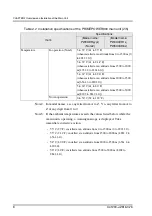
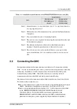
Note2: In model names, x is any letter from A to Z. Y is any letter from A to
Z or any digit from 0 to 9.
Note6: Without the size of the maintenance tray (not used by Fujitsu Siemens
Computers).
Note7: Does not include the sizes of mounting brackets.
Note8: This service area is required for removing the main unit from the rack
for maintenance purposes.
Note9: This dimension depends on the rack in which the main unit is
mounted. Check the specifications of the rack to be used.
Note10: The side service area can be omitted if there is a passage or other
space about 800 mm (31.5 in.) wide that can be used as the service
area.
l
the system administrator’s guide “LAN Console or System Management Console
(SMC) - Installation, Configuration, Operation” (U41584-J-Z916-x-76)
l
and as conceptual information the Section 3.2.2, “LAN connection of the SMC”,
in the “PRIMEPOWER HPC2500/2500/1500/900 Installation Guide”
(U41300-J-Z816-x-76/C120-E162EN) (not directly applicable to the
PRIMESTATION and PW250SMC which are the SMC standard hardware
platforms for enterprise systems supplied by Fujitsu Siemens Computers).
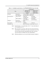
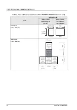
Table 2.2 Installation specifications of the PRIMEPOWER900 main unit (5/5)
Item
Specifications
(Model name:
PW0XDRyyyx)
(Note2)
(Model name:
PW0X0CR1x,
PW0X0CR6x)
Содержание PRIMEPOWER900
Страница 1: ...Edition September 2004 PRIMEPOWER900 ...
Страница 8: ......
Страница 16: ......
Страница 20: ......
Страница 22: ......
Страница 30: ......
Страница 42: ......
Страница 76: ......
Страница 95: ...U41290 J Z816 3 76 65 6 2 Partition Mode Figure 6 3 Correspondence of system boards PCI slots and disks ...
Страница 104: ......
Страница 110: ......
Страница 122: ......
Страница 128: ......
Страница 130: ......
Страница 143: ...U41290 J Z816 3 76 113 C 4 PCI Hot Plug Figure C 4 Rear view of the PCI disk box showing location of PCI slots ...
Страница 166: ......
Страница 174: ......
Страница 176: ......


