background image

24

ADJUSTING IMAGES (PICTURE MENU)

Press 

M E N U

.

The main menu screen will appear.

Press 

 or 

 to select

“PICTURE”.

Each time you press   or  , one of the available
menus appears in the following sequence:

PICTURE 

 POSITION/SIZE 

 OTHERS

Press 

E N T E R

 or 

.

The PICTURE Menu screen will appear.

Press 

 or 

 to select “Tint”.

Press 

E N T E R

 or 

.

The “Tint” adjustment screen will appear.

Press 

 or 

 to change tint

values.

: More green-tinged colors

: More purple-tinged colors

Press 

M E N U

 several times when

you finish.

* Repeat steps 4, 5, and 6 when you wish to make

changes to other options.

1

2

* You can also use the

switches on the display’s
control panel to accomplish
these steps.

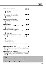
BASIC OPERATIONS [EX. : ADJUSTING TINT (Tint)]

“PICTURE” selected in the main menu
screen

“Tint” selected in the PICTURE Menu screen
(Video Input Mode)

POWER O

N

RGB

VIDEO

WIDE

POWER OFF

VOL

1

2

3

4

SHIFT

MENU

ENTER

You can make changes to all image adjustment options in the PICTURE Menu.

The changes you make will be stored for the selected input mode.  Therefore, you need to select a desired input mode before making any
changes.

3

4

5

6

 ▲

PICTURE 


MENUquit

ENTERnext

 ▲

PICTURE 


Contrast      0 


  −−−−−−−−+

Brightness    0


  −−−−−−−−+

Color         0


−−−−−−−−+

Tint          0


  −−−−−−−−+

Sharpness     0


  −−−−−−−−+

Color temp.      

                     Standard

MENUreturn


Tint      

+30


  −−−−−−−−+

MENUreturn

  adjust

“Tint” adjustment screen

Содержание Plasmavision PDS4208W-B

Страница 1: ...208W B PDS4209U B Before Use Safety Precautions 2 3 Features 4 Accessories 5 Handy Tips 6 Installation 7 Safety Measures 8 Usage Part Names and Functions 9 12 Using the Remote Control 13 Connecting the Display to External Equipment 14 Basic Operations 16 Selecting Input Mode 17 Watching Images on the Wide Screen 18 19 How to Use Menus 20 23 Adjustments Adjusting Images PICTURE Menu 24 25 Adjusting...

Страница 2: ...0 4 2 1995 EN61000 4 3 1996 EN61000 4 4 1995 EN61000 4 5 1995 EN61000 4 6 1996 EN61000 4 8 1993 EN61000 4 11 1994 Safety e EN60950 1992 A1 1993 A2 1993 A3 1995 A4 1997 By conformance with the standard referenced the product follows the provisions of the directives listed below a EC Council Directive 89 336 EEC of 3rd May 1989 b EC Council Directive 92 31 EEC of 28th April 1992 c EC Council Directi...

Страница 3: ...duct and in the operating instructions should be adhered to All operating instructions should be followed Unplug this product from the wall outlet before cleaning Do not use liquid cleaners or aerosol cleaners Use a damp cloth for cleaning Do not use attachments not recommended by the product manufacturer as they may cause hazards Do not use this product near water Do not use immediately after mov...

Страница 4: ...posed to rain or water d If the product does not operate normally by following the operating instructions Adjust only those controls that are covered by the Operation Manual as an improper adjustment of other controls may result in damage and will often require extensive work by a qualified technician to restore the product to its normal operation e If the product has been dropped or damaged in an...

Страница 5: ... of normal size 4 3 aspect ratio images Three different screen sizes in RGB input mode Normal Wide and Zoom are also available Install the display lengthwise The display can be installed lengthwise enabling advertising to be displayed In this case you can set up the display so that on screen information such as input modes and menus is displayed properly Power management function The display featu...

Страница 6: ... Information Cables for connecting the display to external equipment are not supplied Contact your dealer for more information on these products When you run signal cables downwards When you run signal cables to the right One remote control Two AA batteries One user s manual CHECKING ACCESSORIES Manual Four safety brackets types A x 2 type B x 2 Four screws screw A x 2 screw B x 2 Screw B 20 mm Sc...

Страница 7: ...m to function properly when used with other audio visual equipment You may need to move your display if it produces degraded images or noise due to electromagnetic radiation or if the infrared remote control does not function properly Images may not be displayed properly if you connect a non standard PC to the RGB input terminal In this case contact your dealer for more information The protective ...

Страница 8: ...her cables from being accidentally pulled make sure that they run along the wall or through corners The display can be installed with either of its sides facing down Note The display is a highly precise piece of equipment and therefore must be packed properly before transportation Be sure to use only those packing materials originally supplied with the display when repacking it Reference See P 36 ...

Страница 9: ...e wall To do this use screws B 20 mm long to attach safety brackets B supplied with the display to the wall To make sure that the display is stable attach wall brackets at the same height as or slightly lower than the display brackets 3 Tie brackets A and B together To do this use strong cords to fix the display securely to the wall Use two screws supplied with the stand to fix the display using t...

Страница 10: ...red option in a menu POWER POWER MODE WIDE MENU ENTER bottom Front 1 Power indicator lamp This lamp shows whether the main power is ON or OFF as follows Lit red Standby Lit green Power ON Lit orange Power saving DPMS Power saving function mode ON Flashing red Malfunction Flashes differently depending on the type of malfunction See P 40 for more information 2 Remote control signal receiver Receives...

Страница 11: ...s depending on the PC model Contact your dealer for more information 4 RGB synchronization switch SYNC SW TTL ANALOG 75 Ω This switch is used to terminate pins 13 and 14 of the RGB terminal with 75 Ω respectively for receiving horizontal H and vertical V synchronization signals TTL Used when sending RGB signals from the PC to the RGB terminal ANALOG 75 Ω Used when sending analog synchronization si...

Страница 12: ...ch between TTL and ANALOG depending on the types of horizontal H and vertical V synchronization signals received through pins 13 and 14 respectively Pin No Signal 1 DCD Data Carrier Detect 2 RD Received Data 3 TD Transmit Data 4 DTR Data Terminal ready 5 GND Ground 6 DSR Data Set Ready 7 RTS Request To send 8 CTS Clear To Send 9 RI Ring Indication RS 232C terminal RS 232C Description of Input Term...

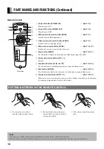
Страница 13: ...e screen over to a desired wide screen 6 Menu button MENU See P 20 35 Use this button to display a desired menu for adjusting the image and sound 7 Volume adjustment buttons VOL Unused 8 Adjustment buttons See P 20 35 Use these buttons to scroll through options in a menu and change values 9 Enter button ENTER See P 20 35 Press this button to finalize the selection of a desired menu or option withi...

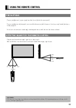
Страница 14: ...nzene or thinner EFFECTIVE RANGE FOR THE REMOTE CONTROL Point the remote control at the display s signal receiver when using it Make sure that there are no obstacles between the remote control and the display s signal receiver USING THE REMOTE CONTROL Information The remote control may not function properly if you use a high frequency fluorescent lamp If you experience problems move the lamp or us...

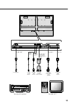
Страница 15: ... check the terminals for position and type before making any connections Loose connectors can result in image or color problems Make sure that all connectors are securely inserted into their terminals Replace the connector cover onto the display when you finish making the connections CONNECTING THE DISPLAY TO EXTERNAL EQUIPMENT Terminal Connector VIDEO INPUT BNC S VIDEO INPUT S terminal COMPONENT ...

Страница 16: ...T COMPONENT VIDEO INPUT color difference input RGB INPUT RS 232C To receptacle To video output terminal To S video output terminal To color difference output terminal To display analog RGB output terminal To RS 232C output terminal Connection to AV equipment ...

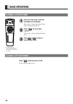
Страница 17: ...hen you do so the power indicator lamp turns green Press or to select a desired input mode BASIC OPERATIONS 1 2 3 You can also use the switches on the display s control panel to accomplish these steps TURNING ON THE POWER Press when the power is ON The power indicator lamp turns red TURNING OFF THE POWER POWER ON RGB VIDEO WIDE POWER OFF VOL 1 2 3 4 SHIFT MENU ENTER ...

Страница 18: ...le you are in RGB input mode 1 You can also use the switches on the display s control panel to accomplish these steps VIDEO INPUT MODE RGB INPUT MODE S video mode Comp video mode Press to select a desired input mode Press the to switch to RGB mode RGB Displays images from equipment connected to the RGB mD sub terminal You can switch between RGB input modes while you are in a video input mode 1 RGB...

Страница 19: ...ly than if you had selected a mode having the same aspect ratio Showing a movie or similar premium event at a different aspect ratio from its original one at any event site restaurant or bar for profit making purposes or for a public audience may constitute a copyright infringement For films try to select a mode having the same aspect ratio as the original image this enables the director s origina...

Страница 20: ... HDTV broadcasting EDTV II enhanced definition television II 4 3 aspect ratio VHF UHF broadcasting BS broadcasting 1 85 1 aspect ratio Vista Vision size 2 35 1 aspect ratio Cinema Vision size Wide2 Video Input Mode Wide RGB Input Mode Reduces the aspect ratio of images from 16 9 to 4 3 Ideal for displaying vertically extended images such as squeezed images and recorded HDTV programs Zoom1 Video In...

Страница 21: ...lected in the main menu screen PICTURE Menu screen Video Input Mode PICTURE Menu screen RGB Input Mode PICTURE MENUquit ENTERnext PICTURE Contrast 0 Brightness 0 Color 0 Tint 0 Sharpness 0 Color temp Standard MENUreturn PICTURE Contrast 0 Brightness 0 Color temp Standard Dot clock 0 Clock phase 0 MENUreturn ENTERnext USING THE PICTURE MENU When you finish selecting a desired option in the PICTURE ...

Страница 22: ...ndard Cool 300 to 300 0 to 15 USING THE POSITION SIZE MENU When you finish selecting a desired option in the POSITION SIZE menu screen press E N T E R or When you do so the adjustment screen for that option appears You can use or and to change the value for the option See P 26 27 Changes you make will be stored only for the selected mode Option 1 Position Function Adjusts screen position Operation...
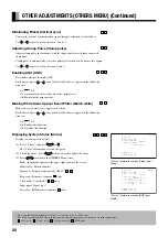
Страница 23: ...us Range On displayed Off not displayed English Deutsch German Español Spanish Français French Italiano Italian 0 no setup 1 2 3 4 NTSC PAL SECAM 4 43NTSC 2 to 1 0 to 8 On auto control Off fixed gain On enabled Off disabled Display only Displays a message screen Enter Displays Extended menu screen Return Returns to OTHERS Menu screen USING THE OTHERS AND EXTENDED MENUS Options with on the right Wh...

Страница 24: ...correction Makes gradation correction Changes number of vertical lines Selects whether to enable auto frequency scanning Operation Use or for switching Use or for switching Use or for switching Display the Screen saver adjustment screen and use or to select an option Use or to switch between available choices for the selected option Use or for switching Use or for switching Display the White peak ...

Страница 25: ...wish to make changes to other options 1 2 You can also use the switches on the display s control panel to accomplish these steps BASIC OPERATIONS EX ADJUSTING TINT Tint PICTURE selected in the main menu screen Tint selected in the PICTURE Menu screen Video Input Mode POWER ON RGB VIDEO WIDE POWER OFF VOL 1 2 3 4 SHIFT MENU ENTER You can make changes to all image adjustment options in the PICTURE M...

Страница 26: ...tinged colors You can adjust color temperature once you have selected Off for Studio mode in the OTHERS Menu You cannot adjust color temperature if you have selected On for Studio mode See P 31 35 Adjusting Dot Clock Dot clock You may find that images blur depending on the clock frequency of your PC s processor If you experience blurring you can obtain a clearer image by adjusting the Dot clock Us...

Страница 27: ...nish Repeat steps 4 5 and 6 when you wish to make changes to other options 1 2 You can also use the switches on the display s control panel to accomplish these steps BASIC OPERATION EX ADJUSTING SCREEN POSITION POSITION SIZE selected from the main menu screen Position selected in the POSITION SIZE Menu screen POWER ON RGB VIDEO WIDE POWER OFF VOL 1 2 3 4 SHIFT MENU ENTER You can make changes to al...

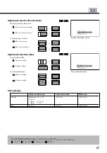
Страница 28: ...s screen to the left Vertical position Vertical Moves screen up Moves screen down Adjusting Screen Size Size Screen width Width Increases width Reduces width Screen height Height Increases height Reduces height Setting Range Position Horizontal 1 Vertical 1 MENUreturn adjust Size Width 1 Height 1 MENUreturn adjust Position adjustment screen Size adjustment screen V R C S V R C S Position Size Vide...
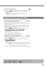
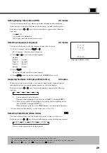
Страница 29: ... make changes to other options 1 2 You can also use the switches on the display s control panel to accomplish these steps BASIC OPERATION EX SELECTING LANGUAGE Language OTHERS selected in the main menu screen Language selected in the OTHERS Menu screen Video Input Mode POWER ON RGB VIDEO WIDE POWER OFF VOL 1 2 3 4 SHIFT MENU ENTER You can make the following changes in the OTHERS Menu Note that cha...

Страница 30: ... individual displays by assigning a unique number to each of the displays Each time you press or one of the available numbers appears in the following sequence 0 1 2 3 4 0 You can normally control displays You cannot control displays if you press any of SHIFT 1 through SHIFT 4 1 4 Allows you to control a desired display by pressing the corresponding button one of SHIFT 1 through SHIFT 4 When you d...

Страница 31: ...ction Off Disables this function Displaying System Status Status V S C R Displays system operation status 1 Select Status and press E N T E R or The Status information screen will appear 2 Check the status Press E N T E R when you wish to update the status 3 Press M E N U to return to the OTHERS Menu screen Mode Input mode appears at the upper right corner of the screen Monitor No Monitor number F...

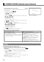
Страница 32: ...WER ON RGB VIDEO WIDE POWER OFF VOL 1 2 3 4 SHIFT MENU ENTER You can use this menu to make adjustments for all extended features You can use the Extended menu screen to make detailed adjustments 3 4 5 DPMS selected in the Extended menu screen Video Input Mode OTHERS OSD On Language Monitor No 0 Video mode Auto AGC On Bkuish white On Status Extended menu MENUreturn ENTERnext More detailed adjustmen...

Страница 33: ...ion picture Still Suitable for watching a still picture Correcting gradation Gradation R You can use this option to make gradation corrections suitable for still or motion pictures Each time you press or one of the available choices appears in the following sequence Mode 1 Mode 2 Mode 1 Suitable for watching motion pictures Mode 2 Suitable for watching still pictures Changing the number of lines d...

Страница 34: ...ou press or one of the available choices appears in the following sequence Off 1 min 3 min 5 min 10 min 30 min Off Disables DPMS Number Time before DPMS starts Unit minutes The power indicator lamp turns orange while the DPMS is ON The power turns ON automatically when the display receives a signal Displaying white over entire screen White screen All modes You can use this option to display white ...

Страница 35: ...reen saver This causes the screen saver pattern to move in the same range at regular intervals When switching between RGB and video input modes frequently 1 Select Mode for Function with Screen saver 2 Select a desired range for Moving area with Screen saver This causes the information displayed to move when you switch between modes EXTENDED FEATURES Extended menu Continued When using the display ...

Страница 36: ...Input priority All modes You can use this option to switch between modes only when a signal is received through the selected input mode terminal You cannot switch the input mode Each time you press or one of the available choices appears in the following sequence Off Video S video Comp video RGB Off Switches between modes normally Other modes Displays images when a signal is received through the s...

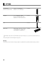
Страница 37: ...ements for that option as given in the relevant instruction manual are met The colors of options do not match the display colors perfectly Warning To prevent injury fire and electric shock arrange for options to be initially installed or installed at a different location by your dealer You can display a wide screen i e 852 dots x 480 lines when you use a graphics board with your IBM PC or a compat...

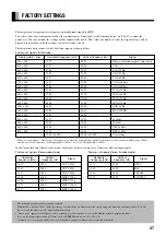
Страница 38: ...640 x 480 31 47 59 94 VGA 640 x 480 37 86 72 81 VGA 72 Hz 640 x 480 37 50 75 00 VGA 75 Hz 640 x 480 43 27 85 01 VGA 85 Hz 720 x 400 31 47 70 09 VGA 400 lines 640 x 400 37 86 85 08 VGA 400 lines 800 x 600 35 16 56 25 SVGA 56 Hz 640 x 400 37 88 60 32 SVGA 60 Hz 800 x 600 48 08 72 19 SVGA 72 Hz 800 x 600 48 88 75 00 SVGA 75 Hz 1024 x 768 48 36 60 00 XGA 60 Hz 640 x 480 35 00 66 67 MAC 13RGB 848 x 480...

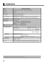
Страница 39: ...als Video image input 1 BNC terminal 1 Vp p 75 Ω S video image input 1 S terminal Y 1 Vp p 75 Ω C 0 3 Vp p 75 Ω Component video input color difference input 3 BNC terminals Y 1 Vp p 75 Ω Pb B Y 0 7 Vp p 75 Ω Pr R Y 0 7 Vp p 75 Ω Applicable systems NTSC PAL SECAM 4 43NTSC PC input terminal RGB input terminal mD sub 3 rows 15 pin Image signal 0 7 Vp p 75 Ω Synchronization signal TTL level or 0 3 Vp ...

Страница 40: ...995 A4 1997 EMC EN55022 1994 Class A EN61000 3 2 1995 EN61000 3 3 1995 EN55024 1998 EN61000 4 2 1995 EN61000 4 3 1996 EN61000 4 4 1995 EN61000 4 5 1995 EN61000 4 6 1996 EN61000 4 8 1993 EN61000 4 11 1994 AS Safety IEC950 A1 A2 A3 A4 EMC AS NZS 3548 Regulation PDS4209U B UL CSA Safety UL1950 CSA C22 2 No 950 EMC FCC Part 15 Class A ICES 003 Class A ...

Страница 41: ...z for XGA Turn OFF the main power switch remove the power plug from the receptacle and contact your dealer for repairs Turn OFF the main power immediately You can turn the power back ON again when the components have cooled sufficiently If the message appears again when you turn the power back on turn off the main power switch remove the power plug from the receptacle and contact your dealer for a...

Страница 42: ...1116 Suenaga Takatsu ku Kawasaki 213 8502 Japan Printed in Japan 8110712004 ...

Отзывы: