MB95630H Series
MN702-00009-1v0-E
FUJITSU SEMICONDUCTOR LIMITED
443
CHAPTER 21 MULTI-PULSE GENERATOR
21.6 Registers
21.6.5.2
16-bit MPG Input Control Register (Lower)
(IPCLR)
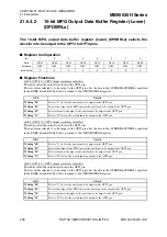
The 16-bit MPG input control register (lower) (IPCLR) controls the input edge
polarity, the noise cancellation function for the SNI2 to SNI0 pins and the edge
detection on the SNI2 to SNI0 pins.
■
Register Configuration
■
Register Functions
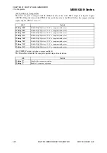
[bit7:6] CPE[1:0]: Input edge polarity select bits
These bits select the input edge polarity for the position detection. The position detection operates according
to the input edge polarity selected by these bits.
[bit5:3] SNC[2:0]: SNI2 to SNI0 noise filter enable bits
These bits determine whether the inputs from the SNI2 to SNI0 pins pass through the noise cancellation
circuit when the inputs are enabled.
The noise cancellation circuit starts the internal n-bit counter when an active level is input (the value of n can
be 2, 3, 4, 5, depending on the settings of the S2[1:0], S1[1:0] and S0[1:0] bits in the noise cancellation
control register). If the active level is held until the counter overflows, the circuit accepts input from the SNI2
to SNI0 pins. Therefore, the pulse width of noise that can be cancelled is about 2
n
machine cycles.
Note: When the noise cancellation circuit is enable, the input becomes invalid in a mode such as stop mode
in which the internal clock is stopped.
bit
7
6
5
4
3
2
1
0
Field
CPE1
CPE0
SNC2
SNC1
SNC0
SEE2
SEE1
SEE0
Attribute
R/W
R/W
R/W
R/W
R/W
R/W
R/W
R/W
Initial value
0
0
0
0
0
0
0
0
bit7:6
Details
Writing "00"
No edge detection (stop state)
Writing "01"
Detection of the rising edge
Writing "10"
Detection of the falling edge
Writing "11"
Detection of both edges
bit5
Details
Writing "0"
SNI2 input does not pass through the noise cancellation circuit.
Writing "1"
SNI2 input passes through the noise cancellation circuit.
bit4
Details
Writing "0"
SNI1 input does not pass through the noise cancellation circuit.
Writing "1"
SNI1 input passes through the noise cancellation circuit.
bit3
Details
Writing "0"
SNI0 input does not pass through the noise cancellation circuit.
Writing "1"
SNI0 input passes through the noise cancellation circuit.
Содержание MB95630H Series
Страница 2: ......
Страница 4: ......
Страница 8: ...iv ...
Страница 20: ...xvi ...
Страница 106: ...MB95630H Series 86 FUJITSU SEMICONDUCTOR LIMITED MN702 00009 1v0 E CHAPTER 6 I O PORT 6 2 Configuration and Operations ...
Страница 282: ...MB95630H Series 262 FUJITSU SEMICONDUCTOR LIMITED MN702 00009 1v0 E CHAPTER 14 LIN UART 14 8 Notes on Using LIN UART ...
Страница 642: ...MB95630H Series 622 FUJITSU SEMICONDUCTOR LIMITED MN702 00009 1v0 E APPENDIX A Instruction Overview A 5 Instruction Map ...
Страница 644: ......


