


1-8
M3099EX/EH OEM Manual
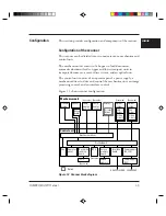
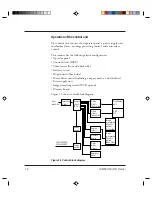
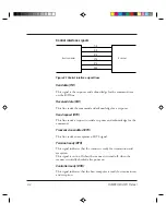
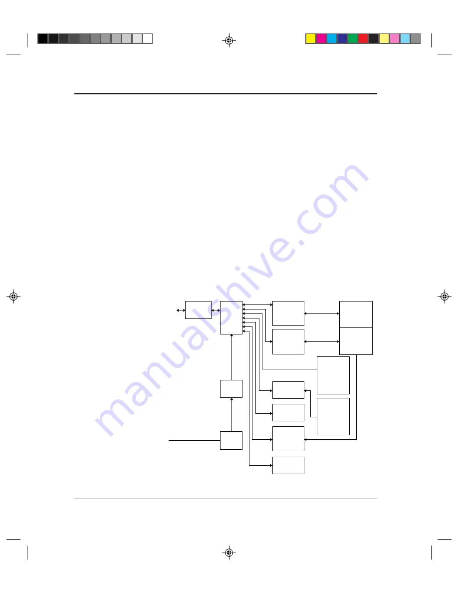
Operation of the control unit
The control unit consists of an operator panel, a power supply unit,
mechanism driver, an image processing control, and an interface
control.
This scanner has the following circuit configuration:
• Operator panel
• Control circuit (MPU)
• Video circuit (front-side/back-side)
• Interface circuit
• Duplex circuit (back-side)
• Motor driver circuit (including a stepper motor, a clutch driver)
• Power supply unit
• Image processing circuit (IPC II option)
• Memory board
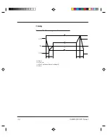
Figure 1.5 shows control block diagram.
Figure 1.5 Control block diagram
Host
machine
Interface
circuit
Control
circuit
(MPU )
Video
circuit
(front-side)
Video
circuit
(back-side)
Image
processing
circuit II
(option)
(front-side)
Duplex
circuit
Memory
board
Motor
driver
circuit
Operator
panel
Mechanism
unit
ADF
MF
Image
processing
circuit II
(option)
(back-side)
Power
supply
Power
switch
100 to 120 VAC
220 to 240 VAC
Содержание M3099EH
Страница 1: ...M3099EX EH IMAGE SCANNER OEM MANUAL C150 E047 02EN ...
Страница 2: ...M3099EX EH IMAGE SCANNER OEM MANUAL ...
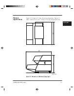
Страница 15: ...M3099EX EH OEM Manual 1 3 OVERVIEW Figure 1 2 1000 sheets hopper type ...
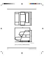
Страница 26: ...2 4 M3099EX EH OEM Manual 610 530 680 Figure 2 2 Dimensions of 1000 sheets hopper type Unit mm ...
Страница 170: ...4 40 M3099EX EH OEM Manual ...
Страница 176: ...5 6 M3099EX EH OEM Manual ...
Страница 196: ...8 10 M3099EX EH OEM Manual ...
Страница 216: ...M3099EX EH OEM Manual B 14 ...
Страница 226: ...IN 4 M3099EX EH OEM Manual ...
Страница 228: ......