


XSCF>
setnetwork
lan#0
-m
255.255.255.0
192.168.1.z
XSCF>
setnetwork
lan#1
-m
255.255.255.0
192.168.2.c
7.5.3
Setting
a
takeover
IP
address
You
can
set
a
takeover
IP
address
for
a
system
that
consists
of
multiple
SPARC
M10-4S
units
and
has
multiple
XSCFs.
The
setting
of
the
takeover
IP
address
enables
takeover
of
the
IP
address
after
switching
of
the
master
and
standby
sides
in
cases
of
XSCF
failover.
By
using
the
takeover
IP
address,
users
can
always
connect
to
the
master
XSCF
without
any
need
to
pay
attention
to
XSCF
switching.
After
setting
the
respective
IP
addresses
for
XSCF-LAN#0
and
XSCF-LAN#1
as
described
in
"
,"
set
one
takeover
IP
address
for
each
pair
of
XSCF-LAN#0
and
XSCF-LAN#1.
(See
(3)
in
and
1.
Set
the
takeover
IP
address
of
XSCF-LAN#0
or
XSCF-LAN#1.
The
following
example
sets
the
takeover
IP
address
192.168.1.z
and
net
mask
255.255.255.0
for
XSCF-LAN#0,
and
the
takeover
IP
address
192.168.2.c
and
net
mask
255.255.255.0
for
XSCF-LAN#1.
7.5.4
Setting
an
SSCP
IP
address
For
a
system
that
consists
of
multiple
SPARC
M10-4S
units
and
has
multiple
XSCFs,
a
network
is
configured
between
the
XSCFs
to
enable
mutual
monitoring
of
states
and
exchange
of
system
information.
The
interface
protocol
of
this
network
is
referred
to
as
the
protocol
for
SP
to
SP
communication
(SSCP).
The
IP
addresses
used
in
this
SSCP
network
are
set
by
default.
However,
if
the
XSCF-LAN
IP
addresses
and
the
default
SSCP
IP
addresses
have
overlapping
network
addresses,
other
values
must
be
set
for
the
SSCP
IP
addresses.
For
details
on
SSCP
IP
addresses,
see
"3.7.5
Understanding
the
IP
addresses
that
are
set
with
SSCP"
in
the
Fujitsu
M10/SPARC
M10
Systems
System
Operation
and
Administration
Guide
.
The
IP
addresses
used
with
SSCP
are
classified
and
set
in
the
following
groups.
These
groups
are
distinguished
by
their
SSCP
link
network
IDs.
At
least
two
IP
addresses
need
to
be
set
for
the
same
SSCP
port.
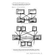
■
Group
with
the
master
XSCF
and
the
XSCF
of
each
BB:
SSCP
link
network
ID
0
(See
(1)
in
■
Group
with
the
standby
XSCF
and
the
XSCF
of
each
BB:
SSCP
link
network
ID
1
(See
(2)
in
■
Group
with
the
master
XSCF
and
the
XSCF
of
each
XBBOX:
SSCP
link
network
ID
2
(See
(3)
in
■
Group
with
the
standby
XSCF
and
the
XSCF
of
each
XBBOX:
Fujitsu
M10/SPARC
M10
Systems
Installation
Guide
・
July
2015
208
Содержание M10 Series
Страница 1: ...Fujitsu M10 SPARC M10 Systems Installation Guide Manual Code C120 E678 12EN July 2015 ...
Страница 10: ...Fujitsu M10 SPARC M10 Systems Installation Guide July 2015 x ...
Страница 156: ...Fujitsu M10 SPARC M10 Systems Installation Guide July 2015 142 ...
Страница 169: ...A B Figure 4 14 Locations for passing cables between the racks Chapter 4 Configuring Building Block Connections 155 ...
Страница 176: ...Fujitsu M10 SPARC M10 Systems Installation Guide July 2015 162 ...
Страница 208: ...Fujitsu M10 SPARC M10 Systems Installation Guide July 2015 194 ...
Страница 240: ...Fujitsu M10 SPARC M10 Systems Installation Guide July 2015 226 ...
Страница 252: ...Fujitsu M10 SPARC M10 Systems Installation Guide July 2015 238 ...
Страница 290: ...Fujitsu M10 SPARC M10 Systems Installation Guide July 2015 276 ...
Страница 310: ...Fujitsu M10 SPARC M10 Systems Installation Guide July 2015 296 ...
Страница 336: ...Fujitsu M10 SPARC M10 Systems Installation Guide July 2015 322 ...
Страница 368: ...Fujitsu M10 SPARC M10 Systems Installation Guide July 2015 354 ...
Страница 374: ...Fujitsu M10 SPARC M10 Systems Installation Guide July 2015 360 ...