background image

 4-7

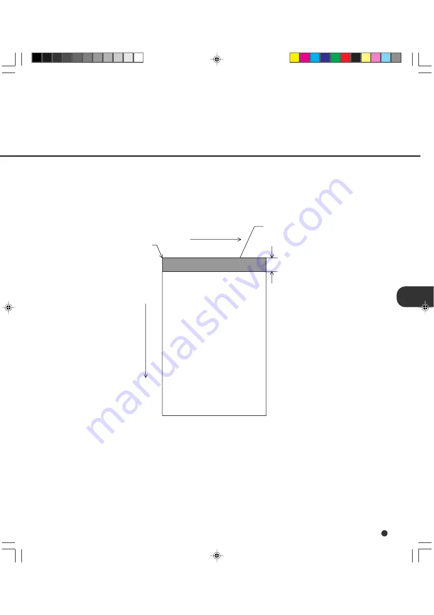
Grounding Color Area

As Figure 4.3 shows, the top 3-mm part of the read area on each surface should be left blank
(grounding color) by specifying a drop-out color. If the drop-out color cannot be specified, select
“Photo” for the document type (linedrawing or photograph).

For details of the drop-out color, see Page 4-8.

Figure 4.3 Grounding color area

Main scanning direction

Reading
reference

Grounding color
(white) or drop-out
color area

3 mm (0.12") 

Subscanning direction

09C4.P65

01.2.17, 5:44 PM

7

Содержание i-4990C

Страница 1: ...C150 E192 01EN i 4990C Image Scanner Operator s Guide ...

Страница 2: ...fi 4990C Image Scanner Operator s Guide ...

Страница 3: ...red to correct the interference at his ownexpense This digital apparatus does not exceed the Class A limit for radio noise emissions fromdigitalapparatussetoutintheRadiointerferenceRegulationsoftheCanadian DepartmentofCommunications Lepésentappareilnumériquen émentpasdebruitsradioélectriquesdépassantles limites applicables aux appareils numériques de la classe A prescridtes dans le Réglesmentsurle...

Страница 4: ... 61 2 9776 4556 HOME PAGE http www fujitsu com au Please send your comments on this manual or on Fujitsu products to the following addresses Asian contact FUJITSU HONG KONG LTD 10 F Lincoln House 979 King s Road Taikoo Place Island East Hong Kong Phone 852 2827 5780 Fax 852 2827 4724 HOME PAGE http www fujitsu com hk FUJITSU KOREA LTD 6th Fl Korea Financial center building Yoido Dong 23 6 Young Du...

Страница 5: ... implied or statutory FUJITSU reserves the right to make changes to any products herein to improve reliability function or design without further notice and without obligation This Product is designed developed and manufactured as contemplated for general use including without limitation general office use personal use and householduse butisnotdesigned developedandmanufacturedascontemplated for us...

Страница 6: ...G INSTRUCTION DOCUMENT SPECIFICATION SPECIFICATIONS and SETUP BROWSE AND TEST MODES Refer to the CD ROM for the information about the routine operation of the fi 4990C The CD ROM contains OPERATING INSTRUCTION CLEANING RE PLACEMENT OF PARTS ADJUSTMENT and TROUBLESHOOTING The fi 4990C is very fast and highly functional image scanner developed for volume filing using charge coupled device CCD image ...

Страница 7: ...procedure correctly CAUTION CAUTION indicates that minor personal injury loss of data or damage to the scanner may result if you do not follow a procedure correctly NOTE NOTE indicates remarks tips and other useful supplementary information The following symbols are used in this manual Used for general WARNING and CAUTION Used for NOTE Conventions 01FI P65 01 2 17 5 39 PM 3 ...

Страница 8: ...FICATION Document Size 4 1 Document Quality 4 2 Document Limitations 4 5 Grounding Color Area 4 7 Drop out Color 4 8 Job Separation Sheet 4 9 q CHAPTER 5 SPECIFICATIONS Installation Specifications 5 1 External Dimensions 5 2 Consumables 5 3 Options 5 4 q CHAPTER 6 SETUP BROWSE AND TEST MODES Setup Browse and Test Modes 6 1 Activating the Setup or Browse Mode 6 2 Contents of the Setup or Browse Mod...

Страница 9: ...TIONS SETUP BROWSE AND TEST MODES GLOSSARY OF TERMS INDEX CHAPTER 1 CHAPTER 2 CHAPTER 3 CHAPTER 4 CHAPTER 5 CHAPTER 6 GLOSSARY OF TERMS SETUP BROWSE AND TEST MODES COMPONENTS INSTALLATION AND CONNECTIONS OPERATING INSTRUCTION DOCUMENT SPECIFICATION SPECIFICATIONS INDEX 01FI P65 01 2 17 5 39 PM 7 ...

Страница 10: ...irmthatallthecomponentshavebeen received Thischapterdescribesthecomponentsofthescanner part names andoperatorpanelarrangementandtheirfunction CheckingtheComponents UnitsandAssemblies Operator Panel Buzzer CHAPTER 1 02C1 P65 01 2 17 5 40 PM 1 ...

Страница 11: ...mponents and must be handled with care Confirm that all the components shown in the following figure have been received Mount the stop lever on the stacker of the scanner If any component is missing please contact your sales agent Operator sGuide this manual and two CD ROMs or Stop lever 03C1 P65 01 2 17 5 42 PM 1 ...

Страница 12: ...ection shows the exterior view and assemblies of the scanner This section also provides names of each part and describes their functions Units 7 6 2 1 16 17 18 19 15 14 13 12 10 9 8 5 4 11 3 17 4 7 22 20 21 03C1 P65 01 2 17 5 42 PM 2 ...

Страница 13: ...top page from document stack 11 Brake roller Separates top page from document stack 12 Upper transport unit Opens for easy access 13 Lever Used to open the upper transport unit 14 Side cover Opens to access back side lamp 15 Stacker Document exit tray 16 Check stopper Adjustable stopper for shorter length documents 17 Stacker guides Helps guide documents into stacker 18 Stop lever Used to keep doc...

Страница 14: ...1 4 Assemblies Guide plate Pad Lower sheet guide assembly Lamp unit back side Lamp Brake roller Pick roller unit Lamp Lamp unit front side 03C1 P65 01 2 17 5 42 PM 4 ...

Страница 15: ... panel is located at the lower right hand side of the scanner The panel consists of an LCD 24 character x 2 line LEDs and buttons Operator Panel DATA CHECK POWER MENU ENTER CANCEL F1 F2 F3 LCD 24 characters x 2 lines 03C1 P65 01 2 17 5 42 PM 5 ...

Страница 16: ...nditions of the scanner Test mode is used for testing the scanner offline Used in setup browse or test mode Clears an error if any Used in setup browse or test mode Lifts the hopper in normal mode without errors Used in setup browse or test mode Lowers the hopper in normal mode without errors Used in setup browse or test mode Used in setup browse or test mode Used in setup browse or test mode Avai...

Страница 17: ...de Manual Feeding Load documents on the hopper table manually Feeding The scanner is feeding documents The second line indicates the number of documents fed per batch Error status display When the scanner detects errors the LCD indicates the following messages There are two types of errors temporary errors and equipment errors Temporary errors Ex The message is cleared just by following the next m...

Страница 18: ...ssed the scanner continues to display the error Button pressed Sounds briefly This sound cannot be disabled by the buzzer setup The scanner has a buzzer to indicate that an error has occurred or an operator panel button is pressed The buzzer function can be set on or off by following the procedure Buzzer in Chapter 6 SETUP BROWSE AND TEST MODES 03C1 P65 01 2 17 5 42 PM 8 ...

Страница 19: ...The chapter describes how to install and connect the scanner Precautions Inspection Cable Connection INSTALLATION AND CONNECTIONS 2 CHAPTER 04C2 P65 01 2 17 5 43 PM 1 ...

Страница 20: ...perate incorrectly Do not install the scanner in a humid dusty or damp places These environments may shorten the scanner life or cause hardware failures Do not place the scanner where liquid spills may occur Be aware of the static electricity Be sure that the flooring and the desk are made of materials that do not generate the static electricity See Chapter 5 SPECIFICATIONS for the information suc...

Страница 21: ...2 2 This section describes how to check the labels Label A An example Inspection Label C Label A Label B Three labels 05C2 P65 01 2 17 5 43 PM 2 ...

Страница 22: ...C PART NO CA04315 B107 MODEL 0 1 2 3 4 5 6 7 8 9 REV 0 1 2 3 4 5 6 7 8 9 0 1 2 3 4 5 6 7 8 9 MODEL fi 4990C IMAGE SCANNER PART NO CA04315 B107 AC100 240V SER NO 1 phase 50 60Hz DATE 2001 02 2 9 1 5A 65 kgf MADE IN JAPAN FUJITSU LIMITED 05C2 P65 01 2 17 5 43 PM 3 ...

Страница 23: ...he device and a power outlet This section describes how to connect the cables Connect the cables as follows Press O side of the main line switch to turn the power off Turning the main line switch off Connecting the power cable Main line switch 05C2 P65 01 2 17 5 43 PM 4 ...

Страница 24: ...les and secure them with hooks or screws NOTE SCSI ID is set to No 5 at shipment Refer to Chapter 6 when changing the setting Connecting the interface cable Interface cable for SCSI Interface connector for SCSI Back side 05C2 P65 01 2 17 5 43 PM 5 ...

Страница 25: ...2 6 Insert the stop lever to the scanner Into the gap in the stacker Attach the stop lever to the scanner 05C2 P65 01 2 17 5 43 PM 6 ...

Страница 26: ...bes how to operate the operator panel basic operation RefertoReferenceGuideaboutinformationonloadingdocumentand opening closingtheuppertransportunit Turning the Power On Basic Operation of the Operator Panel OPERATING INSTRUCTION CHAPTER 3 06C3 P65 01 2 17 5 43 PM 1 ...

Страница 27: ...of the main line switch located at the back of the scanner Press the power switch of the operator panel The power goes on and the green POWER lamp at the operator panel lights Turning the Power On Power switch Operator panel Main line switch 07C3 P65 01 2 17 5 43 PM 1 ...

Страница 28: ...ich you can use setup mode browse mode and test mode Displaying detailed information if an error occurred If an error occurs the CHECK LED blinks and the error message is displayed on the LCD For example the LCD indicates as follows Hopper empty Press CANCEL to clear the error Temporaly errors will clear equipment errors will not 07C3 P65 01 2 17 5 43 PM 2 ...

Страница 29: ...ns no data The scanning operation is not in progress The scanner is not in test mode except the offline feed test and The scanner is not in setup or browse mode The hopper stops at the pick position or at the 250 500 or 1000 sheet position depending on the hopper height adjustment in setup mode At the pick position the top paper of stack the hopper table when no paper is loaded on the hopper is al...

Страница 30: ...be expired For example the following message appears Consumable life alarm AAAAAAAA MMMM In this case press CANCEL The LCD indicates the following message Reset Consumable Counter Yes Enter No Cancel Yes press ENTER The scanner resets the consumable counter to zero No press CANCEL The scanner does not reset the consumable counter In this case the consumable life alarm recurs when the next sheet is...

Страница 31: ...e offline feed test The LCD indicates the numbers as follows Scanning AAAAAAAA MMMM Value Meaning Description AAAAAAAA Abrasion counter Eight columns of numbers indicate the accumulative number of sheets fed by this scanner MMMM Batch counter Four columns of numbers indicate the number of sheets fed per hopper 07C3 P65 01 2 17 5 43 PM 5 ...

Страница 32: ...up function to it This allocation can be done in setup mode After allocation the allocated function can be easily accessed just by pressing the function button For allocatable setup functions see Chapter 6 The function buttons are available when Ready is displayed In details The DATA LED does not light the scanner contains no data The scanning operation is not in progress The scanner is not in tes...

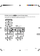
Страница 33: ...U when the LCD indicates Ready or Turn the power on while pressing MENU Available functions differ with the two ways For details see Chapter 6 In the following way you can use the setup mode and browse mode POWER ON Ready MODE SELECT SETUP BROWSE SETUP MODE BROWSE MODE CANCEL ENTER ENTER CANCEL ENTER ENTER SETUP MODE XXXXX BROWSE MODE XXXXX CANCEL ENTER CANCEL ENTER CANCEL CANCEL Please wait CANCE...

Страница 34: ...BROWSE TEST MODE SELECT SETUP BROWSE TEST MODE SELECT SETUP BROWSE TEST SETUP MODE BROWSE MODE ENTER CANCEL CANCEL ENTER ENTER TEST MODE CANCEL ENTER ENTER SETUP MODE XXXXX BROWSE MODE XXXXX TEST MODE Offline Feed Test CANCEL Turn off to quit MODE SELECT ENTER ENTER CANCEL ENTER CANCEL ENTER CANCEL CANCEL CANCEL Cursor buttons Blinking T Please wait 07C3 P65 01 2 17 5 43 PM 8 ...

Страница 35: ...l POWER ON Mode select screen Setup and Browse MENU Setup mode Browse mode Test mode CANCEL Turn power off to quit Ready normal mode POWER ON with MENU ON Mode select screen Setup Browse and Test ENTER CANCEL ENTER CANCEL ENTER CANCEL Error message Error occurred CANCEL Shortcut to setup functions F1 F2 F3 07C3 P65 01 2 17 5 43 PM 9 ...

Страница 36: ...3 10 07C3 P65 01 2 17 5 43 PM 10 ...

Страница 37: ... This chapter describes the document size and document quality of the scanner Document Size Document Quality Document Limitations Grounding Color Area Drop out Color Job separation Sheet CHAPTER 4 08C4 P65 01 2 17 5 44 PM 1 ...

Страница 38: ...e following figure shows document sizes that the scanner can read Minimum Maximum B A A7 size 74 2 9 in x 105 4 1 in Available in both portrait and landscape orientations Unit mm fi 4990C 297 11 7 in Scanner 432 17 in 09C4 P65 01 2 17 5 44 PM 1 ...

Страница 39: ...se use the specified paper In rare occasion double feeding or document damage may occur Fine paper Plain paper OCR paper When using any other paper types of documents place a test batch of documents in to the ADF to see if it successfully feeds the documents NOTE Documents may be damaged when an error occurs Ream weight of paper The ream weight of paper is as follows 52 to 127 g m2 13 9 to 34 lb N...

Страница 40: ... paper Carbon paper Carbonless paper Paper smaller than A7 size or larger than A3 size Other than paper clothes metal foils or OHP films Photographic paper Paper with notches on its side Other than rectangle paper When scanning a translucent document set the density to light mode To prevent roller smudging avoid scanning a document filled out in pencil Clean the roller as often as possible when sc...

Страница 41: ...ightened to fit the condition below More than 30 mm Less than 3 mm Feed direction Feed direction Less than 5 mm Top of the paper More than 30 mm Read surface Read surface When you read curled wrinkled or creased documents documents may not be successfully arranged in the stacker 09C4 P65 01 2 17 5 44 PM 4 ...

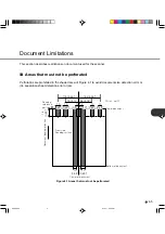
Страница 42: ... document size detection error or job separation sheet detection error or jam 113 4 45 134 5 28 79 3 12 96 3 78 10 0 39 15 0 59 Front side Reading surface Document feeding direction Unit mm Top of document Bottom of document Center of document 10 0 39 Reading reference position 10 0 39 10 0 39 10 0 39 10 0 39 12 0 47 12 0 47 Figure 4 1 Areas that must not be perforated 09C4 P65 01 2 17 5 44 PM 5 ...

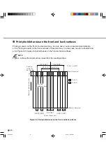
Страница 43: ...Figure 4 2 shows print prohibit areas on the front and back surfaces NOTE Figure 4 2 shows the document as viewed from the reading surface Figure 4 2 Print prohibit areas on the front and back surfaces 113 4 45 134 5 28 79 3 12 96 3 78 10 0 39 15 Document feeding direction Unit mm Top of document Bottom of document Center of document 10 0 39 34 1 34 10 0 39 10 0 39 Area A Area B Reading reference ...

Страница 44: ...g a drop out color If the drop out color cannot be specified select Photo for the document type linedrawing or photograph For details of the drop out color see Page 4 8 Figure 4 3 Grounding color area Main scanning direction Reading reference Grounding color white or drop out color area 3 mm 0 12 Subscanning direction 09C4 P65 01 2 17 5 44 PM 7 ...

Страница 45: ... 4 4 is used to measure print density The measurement must be made in one of the following ways A light source using fluorescent Macbeth PCS meter PCM II is used which requires a filter Figure 4 4 Spectrum band 400 0 10 20 30 40 50 60 70 80 90 100 500 600 700 Waveength nm Relative Spectral Power Drop out color standards In the spectrum of fluorescent lamp the PCS value must satisfy the following s...

Страница 46: ...e 4 5 Shape of document Document type The document type and ream weight specifications given in Section 4 2 apply However the document size shall be A4 or larger 210 mm 8 27 or more wider 15 0 59 Center of document more than 210 8 27 Scanning direction Unit mm 15 0 59 09C4 P65 01 2 17 5 44 PM 9 ...

Страница 47: ...ICATIONS This chapter describes the installation specifications external dimensions consumables option Installation Specifications External Dimensions Consumables Options CHAPTER 5 10C5 P65 01 2 17 5 44 PM 1 ...

Страница 48: ...l endorser 610 24 0 in with optional endorser Temperature 15 to 35 C 20 to 60 C 60 to 95 F 4 to 140 F Phases Single phase Frequency Voltage 100 to 240 VAC 10 Input power Power consumption 250 VA or less Device status Operating Not operating Humidity 20 to 80 8 to 95 Ambient condition 65 143 lb Weight kg Dimensions mm 50 60 Hz 2 4 Width Depth Height 11C5 P65 01 2 17 5 45 PM 1 ...

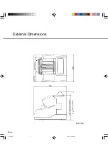
Страница 49: ...5 2 External Dimensions unit mm 11C5 P65 01 2 17 5 45 PM 2 ...

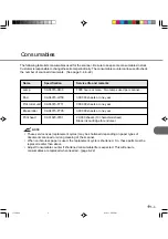
Страница 50: ...k roller unit CA04315 F711 300 000 sheets or one year Brake roller CA04315 F705 300 000 sheets or one year Print head CA01023 0701 20 000 sheets 10 characters sheet Black ink cartridge for endorser NOTE These service lives replacement cycles may be shortened depending on paper types of documents scanned or wrong cleaning of the scanner When carbon less paper is used the replacement cycle is shorte...

Страница 51: ...r Fujitsu sales agent for more information The following table lists options of this scanner Name Specification Remark Endorser CA04315 D201 Ink jet printing method Back side print Max 33 characters 11C5 P65 01 2 17 5 45 PM 4 ...

Страница 52: ...escribes the setup browse and test modes of the scanner Setup Browse and Test Modes Activating the Setup or Browse Mode Contents of the Setup or Browse Mode Activating the Test Mode Contents of the Test Mode CHAPTER 6 12C6 P65 01 2 17 5 45 PM 1 ...

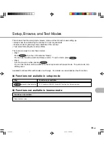
Страница 53: ...setup mode and browse mode To quit a mode press CANCEL Way 2 Turn the power on while pressing MENU You can use the test mode in addition to the setup mode and browse mode To quit a mode turn off the power Available functions differ with modes or with ways For details see descriptions of each function Functions not available in setup mode Way Functions not available MENU pressed in Ready status TP_...

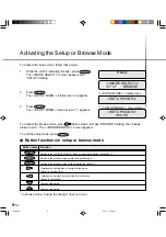
Страница 54: ...ess CANCEL SETUP MODE SETUP MODE Initial screen Ready MODE SELECT SETUP BROWSE SETUP MODE XXXXX SETUP MODE menu screen Button functions in setup or browse mode Button name Function Returns to the SETUP MODE menu screen without saving the change Returns to the previous screen while saving the change Returns to the previous screen without saving the change Displays the next function at the right in ...

Страница 55: ...NTER SETUP MODE XXXXX BROWSE MODE XXXXX CANCEL ENTER CANCEL ENTER CANCEL CANCEL Please wait CANCEL MENU MODE SELECT SETUP BROWSE Cursor buttons Blinking There is another mode selection which enables you to execute the user test on the scanner without the host computer See Activating the Test Mode later in this chapter 13C6 P65 01 2 17 5 45 PM 3 ...

Страница 56: ...nk Counter Reset Description Enables or disables the function which detects a paper length error Enables or disables the function which detects the paper thickness Sets the permissible paper thickness to detect a double feed error Enables or disables the function which detects a skew error Selects a pattern to be set in the image processing option Sets the initial position of the hopper Sets the p...

Страница 57: ...tup mode lock Language White follower mode Interface Board slot SCSI Bus Width setting Printing Position Description Selects the control data transfer rate 2400 4800 9600 or 19200 for the TP interface Sets the SCSI ID of this scanner Sets the product ID of this scanner Enables or disables pre picking Sets the period from when paper is loaded manually to when the pick operation starts Sets the wait...

Страница 58: ...sor buttons Blinking To save the change press ENTER To quit without saving change press CANCEL Paper Length Check OFF 10mm Paper Length Check OFF 10mm Paper Length Check OFF 20mm Paper Length Check OFF 15mm Paper Length Check ON 10mm Transition of screens in setup mode This flowchart indicates the transition of screens in setup mode for reference to the setup operation described in the following p...

Страница 59: ...example of operation when you use this function 1 In SETUP MODE initial screen press ENTER The SETUP MODE menu screen Paper Length Check appears 2 Press ENTER The option select screen indicates the current options with OFF blinking blinking indicates changeable 3 Press or The displayed option changes ON 4 Press The current difference 10 mm blinks blinking indicates changeable 5 Press or The displa...

Страница 60: ...ost computer Remarks OFF Set the double feed check to Disabled Thickness Roller check Detect the double feed by checking the document thickness and the rotation of brake roller Thickness check Detect the double feed by checking the document thickness LCD display Double feed Check Options Off Thickness Check Thickness Roller Default Off At pick the paper Default At pick feed the paper The following...

Страница 61: ...ion select screen appears with the current option TIMING blinking blinking indicates changeable 8 Press ENTER The option select screen appenrs with the current option At pick the paper blinking 9 Press or The displayed option changes At pick feed the paper 10 Press ENTER to save the change The LCD returns to the option select screen appears with the current option TIMING blinking Doublefeed Check ...

Страница 62: ... Paper Length Check Paper Thickness Setup Set the adjustment paper SETUP MODE Paper Thickness Setup Paper thickness setup This function sets the paper thickness which is used as the reference for detecting a double feed error Whether this function is enabled or disabled is determined by the paper thickness check function in setup mode NOTE This setting cannot be displayed in browse mode The follow...

Страница 63: ...ves its value After adjustment the sheet is ejected and the Finished message appears for two seconds then the LCD returns to the SETUP MODE menu screen Paper Thickness Setup If an error for example Mis pick occurs during adjustment remove the paper and press CANCEL The paper load prompting screen appears again Repeat steps 4 and 5 6 Press CANCEL two times The LCD returns to the Ready screen 13C6 P...

Страница 64: ...heck appears 2 Press three times The SETUP MODE menu screen Skew Check appears 3 Press ENTER The option select screen appears with the current option OFF blinking blinking indicates changeable 4 Press or The displayed option changes ON blinks 5 Press ENTER to save the change The LCD returns to the SETUP MODE menu screen Skew Check 6 Press CANCEL two times The LCD returns to the Ready screen SETUP ...

Страница 65: ...ars 2 Press four times The SETUP MODE menu screen IPC 3 Mode appears 3 Press ENTER The option select screen appears with the current setting 0 blinking blinking indicates changeable 4 Press or The displayed option changes 1 2 3 4 5 5 When the desired pattern number appears press ENTER to save the change The LCD returns to the SETUP MODE menu screen IPC 3 Mode SETUP MODE SETUP MODE Paper Length Che...

Страница 66: ...able The horizontal axis shows the density and color of background on paper The vertical axis shows the density of characters or lines Character density Normal 1 Normal back ground and normal character 2 Normal back ground and light character 1 to 5 are pattern numbers NOTE When IPC 3 mode is executed in online status the reading parameter is valid or invalid host setting is invalid as follows Nor...

Страница 67: ...traction X Simplified DTC X Valid Invalid Reading parameter Reading mode X Resolution X Line art Photo X Halftone X Valid Invalid Reading parameter Important When scaned in Grayscale or color this setting is not in Effect only effective when scaned in Binary DTC X Paper Size X Portrait Landscape X Picking X 13C6 P65 01 2 17 5 46 PM 15 ...

Страница 68: ...moves to the 500 sheet position and the new height setting 500 sheets blinks NOTE Each time you press or the hopper moves to the next position and its position is automatically saved Repeat this operation until the hopper is positioned at the desired height SETUP MODE SETUP MODE Paper Length Check SETUP MODE Hopper Height Hopper Height 1000 sheets Hopper Height 500 sheets Hopper height This functi...

Страница 69: ...unction sets the power of the brake roller for stabilizing paper separation in picking documents Remarks Thick strong braking power for thick paper changes according to paper thickness Thin weak braking power for thin paper LCD display Paper Separation Level Options Thick Medium Thick Normal Medium Thin Thin Default Normal If the following errors frequently occur set the braking power as explained...

Страница 70: ...ges Thick to Thin SETUP MODE SETUP MODE Paper Length Check SETUP MODE Paper Separation Level Paper Separation Level Normal Paper Separation Level Medium Thin The following is an example of operation when you use this function Setting Thick Medium Thick Normal Medium Thin Thin Braking power Very strong Strong Medium factory default Light Very light Double feed frequently occurs Mis pick or SF2 freq...

Страница 71: ...Level Ready 5 When the desired option appears press ENTER to save the change The LCD returns to the SETUP MODE menu screen Paper Separation Level 6 Press CANCEL two times The LCD returns to the Ready screen 13C6 P65 01 2 17 5 46 PM 19 ...

Страница 72: ...P MODE initial screen press ENTER The SETUP MODE menu screen Paper Length Check appears 2 Press repeatedly until Drop out Color appears in the lower line of the menu screen 3 Press ENTER The option select screen appears with the current setting Green for Front blinking blinking indicates changeable 4 Press Green current option for Back blinks blink ing indicates changeable 5 Press or The displayed...

Страница 73: ...Default White Back White Black Default White The following is an example of operation when you use this function SETUP MODE SETUP MODE Paper Length Check SETUP MODE Background Changeover Background Changeover F White B White 1 In SETUP MODE initial screen press ENTER The SETUP MODE menu screen Paper Length Check appears 2 Press repeatedly until Background Changeover appears in the lower line of th...

Страница 74: ... can be changed in ten thousands of sheets The least four digits of zeros are automatically added LCD display Consumable Counter Options 10000 to 2560000 sheets Default 2560000 sheets The following is an example of operation when you use this function Background Changeover F White B White 4 Press White current option for Back blinks blinking indicates changeable 5 Press or The displayed option cha...

Страница 75: ...played value changes 1 to 256 Value can be changed in ten thousands of sheets Pressing and holding down or speeds up the change 5 When the desired value appears press ENTER to save the change The LCD returns to the SETUP MODE menu screen Consumable Counter 6 Press CANCEL two times The LCD returns to the Ready screen SETUP MODE SETUP MODE Paper Length Check SETUP MODE Consumable Counter Consumable ...

Страница 76: ... Counter Reset Options YES NO Default The following is an example of operation when you change the setting SETUP MODE SETUP MODE Consumable Counter Reset 1 SETUP MODE initial screen press ENTER The SETUP MODE menu screen Paper Length Check appears 2 Press repeatedly until Consumable Counter Reset appears in the lower line of the menu screen 3 Press ENTER The current option list screen appears with...

Страница 77: ...e counter value reaches to the setting value NOTE You cannot use this function when the setup mode is brought by pressing MENU in the Ready status Remarks Alarm Stop scanning when the accumulated value reaches to the Consumable Counter Setting value the alarm displayes on the LCD and stop the scanning operation Message only When the accumulated value reaches to the Consumable Counter Setting value...

Страница 78: ... appears with Alarm Stop scanning blinking blinking indicates changeable 4 Press or The displayed option changes Message only blinks 5 When the desired option appears press ENTER to save the change The LCD returns to the SETUP MODE menu screen Consumable Alarm Mode 6 To quit the SETUP MODE turn off the power Consumable Alarm Mode Alarm Stop scanning The following is an example of operation when yo...

Страница 79: ...n Paper Length Check appears 2 Press repeatedly until Buzzer appears in the lower line of the menu screen 3 Press ENTER The option select screen appears with the current setting OFF blinking blinking indicates changeable 4 Press or The displayed option changes ON blinks 5 Press ENTER to save the change The LCD returns to the SETUP MODE menu screen Buzzer 6 Press CANCEL two times The LCD returns to...

Страница 80: ...ed in the LCD The following is an example of operation when you use this function 1 In SETUP MODE initial screen press ENTER The SETUP MODE menu screen Paper Length Check appears 2 Press repeatedly until Buzzer Volume appears in the lower line of the menu screen 3 Press ENTER The option select screen appears with the current setting n n q q q q no blinking but changeable 4 Press or The displayed o...

Страница 81: ...ons q q q q q q to Default n n q q q q n n n n n n Symbols of volume may differ from the actual symbols used in the LCD The following is an example of operation when you use this function 1 In SETUP MODE initial screen press ENTER The SETUP MODE menu screen Paper Length Check appears 2 Press repeatedly until LCD Contrast appears in the lower line of the menu screen 3 Press ENTER The option select ...

Страница 82: ...rns to the SETUP MODE menu screen LCD Contrast 6 Press CANCEL two times The LCD returns to the Ready screen SETUP MODE LCD Contrast LCD Contrast Dark n n n q q q Bright Ready Picking speed This function sets the rotational speed of the pick roller Slow speed is recommended when you use thin or flexible paper which is liable to mis pick Remarks LCD display Picking Speed Options Slow Middle Fast Def...

Страница 83: ...screen Picking Speed 6 Press CANCEL two times The LCD returns to the Ready screen SETUP MODE SETUP MODE Paper Length Check SETUP MODE Picking Speed Picking Speed Fast Picking Speed Slow SETUP MODE Picking Speed Ready The following is an example of operation when you use this function TP_IF baud rate This function sets the baud rate signaling speed according to the baud rate of the third party inte...

Страница 84: ...en 3 Press ENTER The option select screen appears with the current setting 9600 blinking blinking indi cates changeable 4 Press or The displayed option changes 19200 2400 4800 5 When the desired option appears press ENTER to save the change The LCD returns to the SETUP MODE menu screen TP_IF Baud Rate 6 To quit the SETUP MODE turn off the power SETUP MODE SETUP MODE Paper Length Check The followin...

Страница 85: ... Paper Length Check appears 2 Press repeatedly until SCSI ID appears in the lower line of the menu screen 3 Press ENTER The option select screen appears with the current setting 5 blinking blinking indicates change able 4 Press or The displayed option changes 6 7 0 1 2 3 4 5 When the desired value appears press ENTER to save the change The LCD returns to the SETUP MODE menu screen SCSI ID 6 To qui...

Страница 86: ...an example of operation when you use this function 1 In SETUP MODE initial screen press ENTER The SETUP MODE menu screen Paper Length Check appears 2 Press repeatedly until Product ID appears in the lower line of the menu screen 3 Press ENTER The option select screen appears with the current setting Fi 4990C blinking blinking indicates changeable 4 Press or The displayed option changes M3099G or M...

Страница 87: ... Press repeatedly until Pre pick ap pears in the lower line of the menu screen 3 Press ENTER The option select screen appears with the current setting ON blinking blinking indicates changeable 4 Press or The displayed option changes OFF blinks 5 Press ENTER to save the change The LCD returns to the SETUP MODE menu screen Pre pick 6 Press CANCEL two times The LCD returns to the Ready screen SETUP M...

Страница 88: ...TER The option select screen appears with the current setting 01 0S blinking blinking indi cates changeable 4 Press or The displayed option changes 00 2S to 29 8S The value changes in 0 2 seconds 5 When the desired value appears press ENTER to save the change The LCD returns to the SETUP MODE menu screen Pick start time 6 Press CANCEL two times The LCD returns to the Ready screen SETUP MODE SETUP ...

Страница 89: ...enu screen Paper Length Check appears 2 Press repeatedly until Manual Feed Timeout appears in the lower line of the menu screen 3 Press ENTER The option select screen appears with the current setting 30 S blinking blinking indi cates changeable 4 Press or The displayed option changes 1 S to 255 S The value changes in seconds 5 When the desired value appears press ENTER to save the change The LCD r...

Страница 90: ...SETUP MODE SETUP MODE Paper Length Check SETUP MODE Paper Pick retry Paper Pick retry Step 2 Times 4 Paper Pick retry Step 2 Times 4 6 Press CANCEL two times The LCD returns to the Ready screen Ready Paper pick retry This function sets the pick motor rotation period and the retry count Remarks 1 to 7 one time to seven times the standard steps 1 to 7 one retry to seven retries LCD display Paper Pic...

Страница 91: ...tor rotation period and the retry count Remarks 1 to 7 one time to seven times the standard steps 1 to 7 one retry to seven retries LCD display Paper Feed Retry Options Step 1 to 7 Default 1 Times 1 to 7 Default 4 1 In SETUP MODE initial screen press ENTER The SETUP MODE menu screen Paper Length Check appears 2 Press repeatedly until Paper Feed retry appears in the lower line of the menu screen SE...

Страница 92: ... ENTER The option select screen appears with the current setting 1 for Step blinking blinking indicates changeable 4 Press The current count setting 4 blinks 5 Press or The displayed option changes 1 2 3 4 5 6 7 6 When the desired value appears press ENTER to save the change The LCD returns to the SETUP MODE menu screen Paper Feed retry 7 Press CANCEL two times The LCD returns to the Ready screen ...

Страница 93: ...which enables you to access the allocated setup function just by pressing the button whenever the scanner is in the Ready state This function is valid even in the setup mode lock state refer to the next function However the F1 F2 and F3 buttons are invalid in setup browse and test modes The following is an example of operation when you allocate START and EJECT keys to the F1 and F2 buttons respect...

Страница 94: ...ndefined F2 selection EJECT key Function Key F1 F2 F3 6 When START key is displayed press ENTER The LCD returns to the function key select screen with F1 blinking 7 Press once F2 blinks 8 Press ENTER The F2 selection screen appears with the current setting Undefined blinking blinking indicates changeable 9 Press or The setup functions START key and EJECT key are displayed in sequence at the lower ...

Страница 95: ... to save the change The LCD returns to the SETUP MODE menu screen Setup Mode Lock 6 To quit the SETUP MODE turn off the power SETUP MODE SETUP MODE Paper Length Check SETUP MODE Setup Mode Lock To cancel the setup mode lock state turn off the power and turn on the power while pressing the MENU button to enter the setup mode In the setup mode select the Setup Mode Lock function and set the option t...

Страница 96: ...links 5 When the desired option appears press ENTER to save the change The LCD returns to the SETUP MODE menu screen Language 6 Press CANCEL two times The LCD returns to the Ready screen SETUP MODE SETUP MODE Language Language Language English SETUP MODE language The following is an example of operation when you change the setting Language This function is to set the LCD display English or Japanes...

Страница 97: ...ound in the scanner is regarded as the white reference 1 The leading paper of the paper is regarded as the white reference LCD display White follower mode Options 1 0 Default The following is an example of operation when you change the setting 1 SETUP MODE initial screen press ENTER The SETUP MODE menu screen Paper Length Check appears 2 Press repeatedly until White follower mode appears in the lo...

Страница 98: ...y until Interface Board Slot appears in the lower line of the menu screen SETUP MODE The following is an example of operation when you use this function Interface board slot This function activates one interface board while 2 interface boards are mounting NOTE You cannot use this function when the setup mode is brought by pressing MENU in the Ready status Remarks LCD display Interface Board Slot O...

Страница 99: ... SCSI board prohibits a transfer of the 16 bit width data set the 8 bit instead You cannot use this function when the setup mode is brought by pressing MENU in the Ready status 3 Press ENTER The option select screen appears with the current setting AUTO blinking blinking indicates changeable 4 Press or The displayed option changes SLOT 1 or SLOT 2 blinks 5 When the desired option appears press ENT...

Страница 100: ...r The displayed option changes 8 bit 5 Press ENTER to save the change The LCD returns to the SETUP MODE menu screen SCSI Bus Width Setting 6 To quit the SETUP MODE turn off the power SETUP MODE SETUP MODE SCSI Bus Width Setting SCSI Bus Width Setting 8 bit SCSI Bus Width Setting 16 bit The following is an example of operation when you use this function Remarks LCD display SCSI Bus Width Setting Op...

Страница 101: ...ait MODE SELECT SETUP BROWSE TEST MODE SELECT SETUP BROWSE TEST TEST MODE Offline Feed Test TEST MODE menu screen Button functions in test mode Button name Function Returns to the TEST MODE menu screen Executes the test Returns to the previous screen Displays the next lower level screen Returns to the previous screen without saving the change Displays the next function at the right in the menu Mov...

Страница 102: ...SE MODE ENTER CANCEL CANCEL ENTER ENTER TEST MODE CANCEL ENTER ENTER SETUP MODE XXXXX BROWSE MODE XXXXX TEST MODE Offline Feed Test CANCEL Turn off to quit MODE SELECT ENTER ENTER CANCEL ENTER CANCEL ENTER CANCEL CANCEL CANCEL Cursor buttons Blinking T Please wait Mode selection power on with MENU pressed 15C6 P65 01 2 17 5 47 PM 50 ...

Страница 103: ...DC C Interface farmware Sensor status Displays the status of the sensors Sensor adjustment Changes the current and slice level of sensors to adjust the sensors white balance adjustment Adjust the Amp Gain Value for R G B when put the white paper in to scanner 5V voltage check Displays the voltage of 5 volts EEPROM edit Writes arbitrary data in EEPROM address 00 to FF to confirm or change the set v...

Страница 104: ...king indicates selectable Offline feed test This function scans sheets of paper continuously for checking entire operation of the mechanism without a host computer You can use the Settings function in setup mode to modify scanning parameters scanning mode paper size orientation density resolution and halftone processing for scanning documents Remarks START begins the test SETUP changes settings of...

Страница 105: ...TART blinks blinking indicates selectable 12 Press ENTER The scanner feeds and scans documents continuously until it detects an error usually Hopper empty During feeding the upper line indicates Feeding and the lower line indicates the number of sheets fed To halt the test press CANCEL To restart the test press ENTER To restart from a hopper empty status put sheets of paper on the hopper table and...

Страница 106: ...power Options This function displays the options installed in the scanner LCD display Options Displayed options Endorser When an option is installed ON is displayed under the option When an option is not installed OFF is displayed under the option The following is an example when you use this function Remarks Endorser printer that prints back side of documents TEST MODE TEST MODE Offline Feed Test...

Страница 107: ...hich the lamp is lit since the scanner has been installed These values are helpful for estimating the life of devices LCD display Device Life Displayed devices COUNT LAMP F and LAMP B The unit of each value is not displayed on the LCD The following is an example operation when you use this function Remarks COUNT accumulative number of sheets fed LAMP F accumulative number of operating hours for th...

Страница 108: ...6 56 15C6 P65 01 2 17 5 47 PM 56 ...

Страница 109: ...c start mode manual start mode In this mode the reading operation is activated only by START command Back side reading Back side scanning Refers to reading the back side of the document specifically in Duplex reading mode Bit The smallest unit of information in computer memory A bit is a single digit either a 1 or a 0 in the binary numbering system Eight bits equal one byte Browse mode The mode in...

Страница 110: ...density and that of adjacent pixels are summed with black pixels relocated in their order of density as they relate to adjacent pixels The purpose of this technique is to minimize the average error between read and printed densities Density data for adjacent pixels is modified by diffusing errors on the objective pixel into several pixels which are then binarized This maintains high grayscale leve...

Страница 111: ...or lighter but not completely white areas adjacent to black areas Weakening this emphasis eliminates spot noise or produces softened images Image processing An image is read with specified parameters Initial screen A screen displayed when the power is turned on or when reading is activated by the command from the host computer Interface The connection that allows communication from one part of a s...

Страница 112: ...and line art images Manual Feed mode Manual Mode Requires the operator to feed each document manually to the hopper table Mirror image The read image is symmetrically flipped to produce a mirror image of the original detected in the main scanningdirection Noise removal Isolated noise from an image appearing as black spots in white areas and voids in black areas is removed to improve image quality ...

Страница 113: ... of the document until picking starts after the document passes the hopper empty sensor Picking time The period from the start of picking until the document reaches SF1 sensor Specify a little longer picking time for the document with a large friction factor Pick speed A speed when a document is picked Set the pick speed to SLOW to prevent JAM or MISS PICK Portrait A document is transported and re...

Страница 114: ...F1 sensor The document detection sensor It detects the light that transmits the paper It also detects the double feederror Simplex reading mode Only the front side of the document is read in this mode Place the documents face up at the center of the hopper table Smoothing Smoothing eliminates jaggies from slanted lines and curves Irregular convexities are deleted and irregular concavities filled i...

Страница 115: ... alarm 3 4 Confirmingthenumberofsheetsprocessed by the scanner 3 5 Connecting the interface cable 2 5 the power cable 2 4 Consumable alarm mode 6 25 INDEX A Consumable counter 3 4 6 22 Consumable counter reset 6 24 Consumable life alarm 3 4 Consumables 5 3 Contents of the Setup Mode 6 4 Test Mode 6 51 Conventions iii Curl of paper 4 3 Cursor buttons 1 6 6 2 6 49 DATA LED 1 6 Device life 6 55 Diffe...

Страница 116: ...ne switch 1 3 2 4 3 1 Manual feed timeout 6 37 MENU button 1 6 3 7 6 2 6 49 Mis pick 6 18 6 30 Mode selection MENU pressed in Ready status 6 3 power on with MENU pressed 6 50 OCR paper 4 2 Offline feed test 6 52 Operation status display 1 7 Operator s Guide 1 1 Operator panel 1 3 1 5 3 2 Options 5 4 Options setup item 6 54 Pad 1 3 1 4 5 3 Paper curl of 4 3 Paper feed retry 6 39 Paper length check ...

Страница 117: ... 17 Paper thickness setup 6 10 Pick start time 6 36 Picking speed 6 30 Pre pick 6 35 Product ID 6 34 SCSI Bus width setting 6 47 SCSI ID 6 33 Setup mode lock 6 42 Skew check 6 12 TP_IF baud rate 6 31 White follower mode 6 45 Setup mode 3 7 6 1 Setup mode contents of 6 4 Setup mode lock 6 42 SF2 did not detect leading edge of paper 6 17 Side cover 1 3 Skew check 6 12 Specifications 5 1 Stacker 1 3 ...

Страница 118: ...IN 4 Upper transport unit 1 3 Using the function buttons 3 6 Using the setup browse and test modes 3 7 VDC C revision 6 51 Weight 5 1 White follower mode 6 45 White balance adjustment 6 51 W V ...

Страница 119: ...18CE P65 01 2 17 5 48 PM 1 ...

Страница 120: ...This manual uses recycled paper C150 E192 01EN fi 4990C Image Scanner Operator s Guide fi 4990C Image Scanner Operator s Guide ...

Отзывы: