CHAPTER 4
ETSI Configuration
Overview
FNC-7500-0061-200
Issue 1, May 2009
FLASHWAVE 7500 Release 6.1
Equipment Installation
4-2
Fujitsu and Fujitsu Customer Use Only
4.1
Overview
This chapter provides prerequisites and procedures for installing a rack and installing or
connecting the shelves, plug-in units, and cables that make up the FLASHWAVE® 7500 ETSI
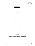
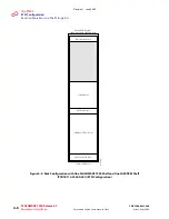
Configuration system. This chapter also describes the basic rack configurations for the
FLASHWAVE 7500 ETSI Configuration system. Procedures for attaching cables to the
Optical/Tributary shelf are provided in
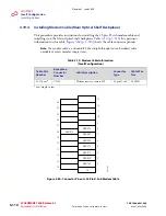
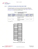
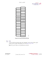
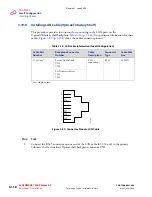
Section 4.16, Installing Cables [p. 4-77]
Note:
In an ETSI Configuration, the Optical/Tributary shelf is the ETSI shelf (FC9682SHU4). The
name of a specific shelf depends on its function as determined by the connections to its station
interface area (SIA) and the plug-in units installed. An Optical shelf supports the main ring
wavelength division multiplexing (WDM) facilities; a Tributary shelf provides client services.
The information contained in the following sections applies to the ETSI 40-Ch WSS
Configuration application.
Before performing the installation procedures, review the following subsections describing
prerequisites, standard rack configurations, and flange kits.
4.2
Prerequisites
Ensure that all FLASHWAVE 7500 ETSI Configuration equipment has been received, and all
data forms and job engineering drawings have been completed and are available.
The tools required for performing procedures listed in this chapter include the following:
■
Common hand tools
■
Digital multimeter (DMM)
Revision 1, June 2009
Содержание FLASHWAVE 7500
Страница 8: ...Revision 1 June 2009 ...
Страница 10: ...Revision 1 June 2009 ...
Страница 16: ...Revision 1 June 2009 ...
Страница 362: ...Revision 1 June 2009 ...
Страница 386: ...Revision 1 June 2009 ...

